Reducing nRF5340 Power Consumption during nRF7002 TWT Intervals

I am using the nRF7002DK development board, which features an nRF5340 as the Host MCU for the nRF7002 chip. I am testing the "Wi-Fi TWT Sample" sample project, which allows me to establish a Target Wake Time (TWT) session between the nRF7002 Wi-Fi module and a Wi-Fi 6 Access Point.

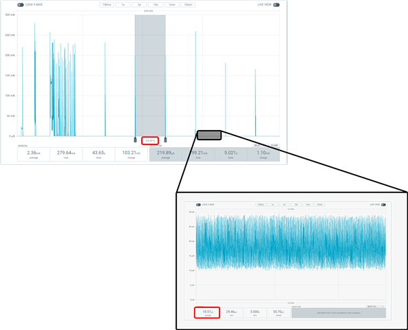
In this particular case, I have configured a TWT interval of 5 seconds. During the time interval between two TWT pings, it is observed that the nRF7002 is in Sleep Mode with a consumption of 18uA, as indicated in its datasheet and the image shown below:
nRF7002 Consumption

However, for my development project, it is a requirement that, between two TWT pings, the nRF5340 Host MCU maintains an average current lower than that presented in the following image (currently at 158uA).
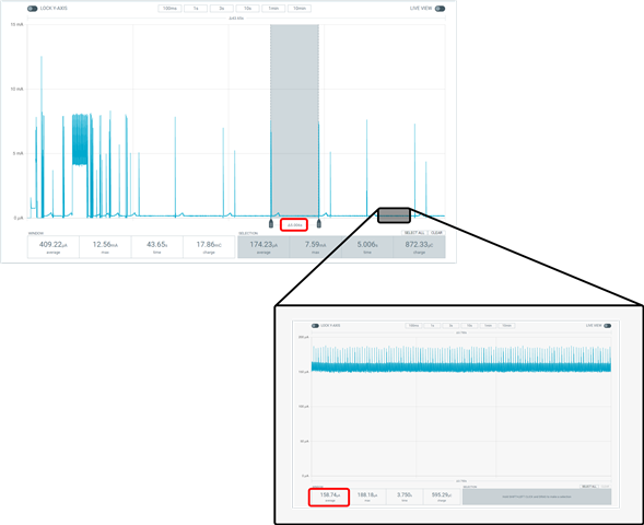
nRF5340 Consumption

Could you please guide me on any configuration settings for the nRF5340, either in its QSPI interface or its Sleep modes, to reduce the average current consumed by this MCU between TWT intervals?

Parents
  • Hi Holman

    What kind of setup are you using for the measurements? 

    Could you share a diagram or picture showing how the PPK2 is connected? 

    The current draw of the nRF5340 host should be around 18uA in between TWT events, not as high as 158uA. 

    Best regards
    Torbjørn

  • Hi!

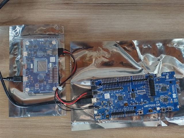
    The PPK2 is connected to a nRF7002-DK such that I only can measure the nRF5340 consumption connecting the pin PPK2 VOUT (red wire) to the "->" pin of P22 terminal of the DK, while the PPK2 VIN (brown wire) is connected to the "<-" pin of P22. The PPK2 is configured as "Ampere Meter" to take the measurements. The DK USB terminal is connected to an USB port of my PC, and the same for the USB port of the PPK2. Additionally, the SW6 switch of the DK is set to "DISABLE".

    Finally, the PPK2 GND (black wire) is connected to the "-" terminal of P21.  


    Remark: I am using the nrf7002-DK PCA10143 version.    

    Measurement Setup

    Thank you and best regards.

    Holman.

  • Hi Holman

    Sorry for the slow response.

    Myself I have only run tests as described here using P23. Without TWT enabled I typically get average currents in the tens of milliamps, and once TWT is enabled the base current drops to less than 20uA. 

    Have you tested yourself using this method, with no other modifications to the DK? 

    Best regards
    Torbjørn

  • Hi Torbjørn,

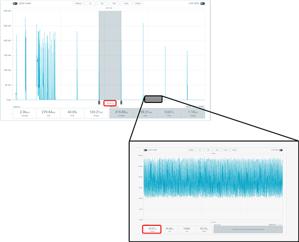
    Based on the link you cited, I have tested it applying all the steps of that webpage with no other modifications. But applying the link steps, I measured the current of the nRF7002 Companion IC instead of the nRF5340 current. However, the obtained measurements with the link indications are near of 20uA as you say, and it corresponds to the following picture:


    The issue is related to the nRF5340 current measurement, where the current between TWT events is near of 150uA. To measure the current only in the nRF5340 MCU, I applied the steps given here with the difference that I didn't connect the "Second PPK2" because I only have one Power Profiler Kit. Instead of using the "second PPK2", the Jumper cap is connected in P23 because I don't need to measure the current on the nRF7002 companion IC.

    Best Regards.

Reply
  • Hi Torbjørn,

    Based on the link you cited, I have tested it applying all the steps of that webpage with no other modifications. But applying the link steps, I measured the current of the nRF7002 Companion IC instead of the nRF5340 current. However, the obtained measurements with the link indications are near of 20uA as you say, and it corresponds to the following picture:


    The issue is related to the nRF5340 current measurement, where the current between TWT events is near of 150uA. To measure the current only in the nRF5340 MCU, I applied the steps given here with the difference that I didn't connect the "Second PPK2" because I only have one Power Profiler Kit. Instead of using the "second PPK2", the Jumper cap is connected in P23 because I don't need to measure the current on the nRF7002 companion IC.

    Best Regards.

Children
  • Hi Holman

    I am trying to reproduce your findings, but in my case the average currents seem to be quite a bit higher. Did you make any significant changes to the project configuration before running your tests, other than to set the TWT wake interval to 5 seconds? 

    Best regards
    Torbjørn

  • Hi Torbjørn,

    I forgot to mention that I applied the following configuration in the prj.conf to disable the logging through the VCOM, according to the recommendations here:

    CONFIG_SERIAL=n

    It reduces the current consumption on the nRF5340 MCU. 

    Thank you! 

  • Hello Torbjørn,

    Could you give some update for this case please? I would appreciate any help you can provide.

    Thank you!

    Holman. 

  • Hello Holman, and sorry about the delay. Torbjørn is currently OOO, and I'll be taking over this case.

    Is there any development to this case, or are you still trying to get the consumption down? If I am understanding this case correctly, you are currently getting 158uA and trying to get it down to 18uA between the TWT intervals? 

    Regards,

    Elfving

  • Hello Elfving,

    Thank you for your response. Unfortunately, there hasn't been any progress in this case yet. The primary issue revolves around the power consumption of the Host MCU nRF5340 between Target Wake Time (TWT) intervals.

    The nRF7002 Companion IC has a power consumption of 18uA, which aligns with the reference manual for this chip, and there are no issues with it.

    However, in my project, I require the Host MCU (nRF5340) to have reduced power consumption as well. Currently, the nRF5340 has a power consumption of 158uA between TWT intervals, but I need this figure to be lower. According to the reference manual, I understand that the nRF5340 in sleep mode could achieve a consumption in the tens of uA range. Is there any way to reduce the power consumption of the nRF5340 between TWT intervals?

    Thank you and Best Regards.

    Holman.

Related