SPI transfers cause BLE connection timeout, but only on some units and especially when cold?

I'm running into a wall trying to find the root cause of a problem that we only started noticing after a small production run of a custom device built around the nRF52840 (specifically the Rigado/u-blox BMD-340 module).

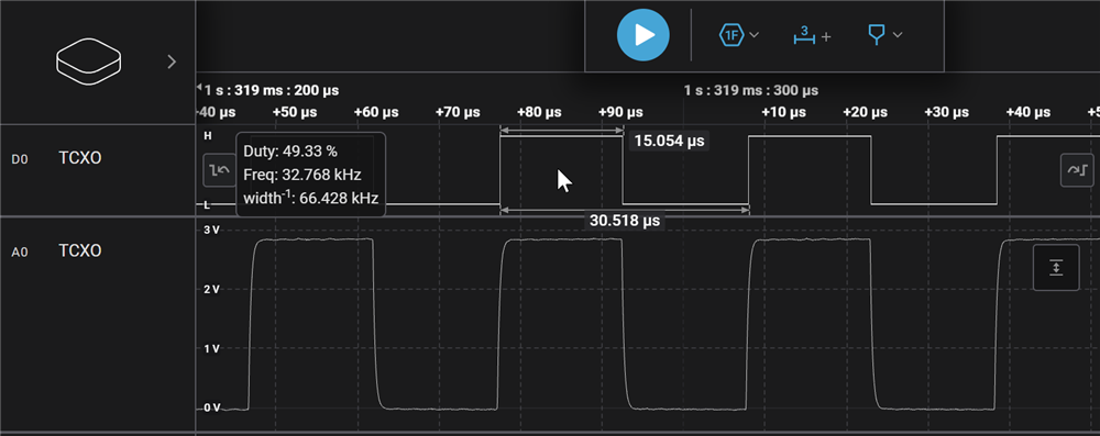
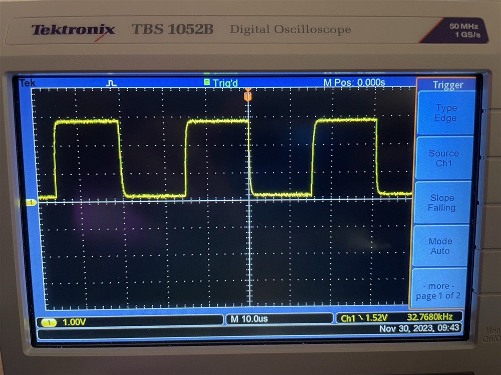
In short, we have an IMU on the board (Hillcrest/CEVA BNO085) communicating over SPI at 2MHz, and when we actually use the IMU (read ~16-byte bursts about 400 times/sec), the BLE connection drops with a 0x08 timeout error. If we don't communicate with the IMU, we can maintain a stable connection as long as we want. Both the IMU and the Bluetooth module are being driven by the same external SiTime 32768Hz TCXO (SIT1552AI-JE-DCC-32.768E). This signal looks perfectly clean on all units, as far as I can measure--though I may not have the right equipment to measure adequately.

The problem only happens on about 5% of the units we built, and not always in equal severity. Most of our devices have no issues. The ones that exhibit this problem often do so rarely, with only two that we've found so far exhibiting it every time, right away, as soon as we connect and start using the IMU. I have one of these on my desk in a test jig.

I'm using SoftDevice S140, v7.2.0, SDK 17.1.0. In addition to the radio, I've also configured TWI(0), SPI(1), and SPI(2). Currently, only SPI(1) is actively used. SPI(1) goes to a different peripheral IC that is currently not implemented in firmware. In case it's relevant, the SPI pins in question are P1.13 (MISO), P1.14 (MOSI), and P1.15 (SCK). The CS pin for the slave device in question is P1.12.

Let me walk you through my troubleshooting efforts.

1. I am certain the disconnection reason given is a supervision timeout. I have plenty of debug output in place to confirm this. Other than that error code in the disconnection event, there aren't any other helpful SoftDevice debug logs generated, even when the SD log level is set to debug (4).

2. I've captured multiple sniffer traces using a nRF52840 USB dongle and Wireshark, but nothing helpful came of that. All it shows is normal communication up until the peripheral simply stops transmitting, then resumes advertising as intended after a disconnection. There's no catastrophic crash, hard fault, or watchdog reset (WDT expires after 2 seconds); the firmware seems to keep humming along fine other than the loss of BLE communication, but it will happily reconnect again afterwards.

3. I've tried sending dummy data over the BLE connection at the same rate as what we capture and process from the IMU (~3200 bytes/sec), and the data transfer itself doesn't appear to cause any issues. I can do that all day long, and it stays connected. Further, if I simply gather data from the IMU over SPI but don't send it over the air, the connection still drops.

4. My non-blocking SPI transfer uses a volatile "xfer_done" boolean in the event handler, and uses "sd_app_evt_wait()" in a while loop until the transfer finishes to ensure the SD doesn't get ignored. I was previously using "_WFE()" instead, and I was really hoping that change would fix it, but it had no effect.

5. I've tried using both blocking and non-blocking SPI master implementations. My sdk_config.h has EASY_DMA enabled, but I'm not using the new NRFX_SPIM implementation. Should I change this?

6. After stumbling across this post from earlier in 2023, I tried using a heat gun on my test device to warm it up significantly (probably 40 deg. C, room temperature is more like 25 deg. C), AND IT STARTED WORKING. Once it cooled down again, the instant-timeout issue came back. This is the most interesting result so far, because it actually explains some behavior we saw but couldn't figure out--namely, the first time we really noticed the problem was during some tests involving outdoor use, where it was cooler than indoors. BUT WHY? Although I can see why temperature could affect a clock signal and therefore link stability, why would it ONLY matter if the IMU is in use via the SPI peripheral?

7. Changing the LFCLK source to SYNTH in sdk_config.h eliminates the problem entirely, at the expense of current consumption. This is why I still suspect that the clock has something to do with it. But I can't figure out what could be wrong.

I'm at a loss what to measure, test, or try at this point. Do any of you wonderful people have any ideas? I am happy to provide more detail on any point if needed.

Parents
  • How exactly is the LFCLK source configured in your application? The SoftDevice does not have any option for configuring external clock source, but if clock is configured and started by the application before the SoftDevice is enabled, the EXTRENAL/BYPASS configuration should not be overridden.
    Can you provide details of the TCXO and an accurate scope (not logic analyser) trace of the TCXO waveform at the nRF52?

    Thanks for your replies, and my apologies--I've updated the original post with more detail about the part. It's SIT1552AI-JE-DCC-32.768E, specifically chosen for the rail-to-rail full swing and extra high accuracy. We have not requested or configured a non-standard VOH/VOL value, so my understanding (and intent, and measurement) is that it's simply GND to VCC. Note, VCC in this circuit is 3.1V.

    The TCXO clock output is connected to P0.00 (XL1) through a 1K series resistor. (The signal appears to be the same on both sides of this resistor). P0.01 (XL2) is left floating. The LFCLKSRC register is configured at the top of the bootloader's main() function to full-swing mode (EXTERNAL + BYPASS bits as defined in nrf_clock.h):

    // configure LFCLK if necessary
    if (!nrf_clock_lf_is_running())
    {
        // set LFCLK source to external full-swing clock
        NRF_CLOCK->LFCLKSRC = NRF_CLOCK_LFCLK_Xtal_Full_Swing;
    }

    It checks to make sure the clock isn't running first because sometimes the app jumps back to the bootloader for DFU. The same conditional configuration block of code is in the application's main() function as well, as I've currently been using an app-only firmware image for simpler/faster testing and debugging in Segger Embedded Studio + J-Link.

    The bench tools I currently have available are a Saleae Logic Pro 16 (digital + analog) and a Tektronix TBS 1052B digital oscilloscope, neither of which is the world's best clock measurement tool, but here's what I get:

    Both devices show basically what I expect to see, though the rails aren't quite touched according to the Tektronix scope--just close. There is also a fairly large variance in what the Saleae shows for the actual clock period. The screenshot highlights a detected frequency that is exactly correct, but the analyzer reports a range of 32688 up to 32860 Hz. I suspect a measurement issue rather than a signal issue because (1) the Tektronix unit is much more stable and (2) one of our devices that works fine with a stable connection yields the same varied measurement on the Saleae device.

    If there is a specific tool I need to capture this better, let me know; I might be able to get one.

    I'm intrigued by the possibility of measuring the TCXO against the 32 MHz clock, and may dig into this. Another question is whether it could be possible to switch clock sources at runtime for power-saving purposes. The increased consumption of the HFCLK is dwarfed by the power draw of active components like the BLE radio and IMU during normal active use of our device, so it would be acceptable to use the HFCLK for BLE connection timing and drop back to the LFCLK for extended sleep (minutes/hours) in between usage events.

    Speaking of temperature dependence (which clearly impacts the behavior in my case), here are three more data points:

    1. I tried the most aggressive clock setting (20ppm accuracy) and then used a hot air gun to slowly raise the temperature of the whole board up to about 70 deg. C. This allowed a solid connection with full IMU use and data transmission for five minutes, which is when I stopped the test

    2. I then tried putting a small plastic bag with some crushed ice directly on the test device to force it to misbehave. Starting from the warm state, it retained the connection for another four minutes before it timed out. Reconnecting immediately allowed another semi-stable connection, lasting 50 seconds that time. Reconnecting again only lasted about 10 seconds, clearly getting progressively worse as the temperature dropped.

    3. I let the ice sit on it for another 30 minutes until it was much colder than usual, at which point not only would it immediately disconnect after connecting + starting the IMU, but the small double-beep disconnection tone was sluggish and drawn out. This is an audible signal we generate via PWM into a piezo element (low-side transistor switch, not direct), implemented using the "app_pwm" driver. By "sluggish," I mean that the tone's pitch was correct but it's supposed to be two 100ms beeps with a 100ms gap between, and all three of those durations were more like 1500ms. So, the app timer ticks got way slower somehow, presumably because they're driven by the LFCLK as well. But the LFCLK definitely hadn't dropped down to 10kHz or 3kHz or something, or the whole system would have fallen apart.

    I'm still confused.

  • Looks correct; however I would try shorting out the 1k0 series resistor and see if there is any change. A periodic check in the firmware for the contents of LFCLKSRCCOPY and LFCLKSRC and LFCLKRUN would also be a good idea ..

    .. I should add that with a 1k0 resistor the high-impedance nRF52840 clock input pin will experience more interference from a high-speed clock source such as SPI ..

    Edit: I looked at the BMD340 and the SCK and Osc pins are pretty close together, plus the P1.15 SCK is unsuitable for any kind of SPI clock; it is close to the radio and will affect as well as be affected by transmissions. So .. the fix - if shorting the 1k doesn't work - may well be to use an unrestricted P0.nn i/o pin for SCK (and probably MOSI and MISO as well).

    WLCSP Port  BMD340 Function
    ===== ===== ====== =======================================================================================
    B9    P0.00 Pin 13 XL1 Digital I/O Analog input General purpose I/O Connection for 32.768 kHz crystal
    B10   P0.01 Pin 14 XL2 Digital I/O Analog input General purpose I/O Connection for 32.768 kHz crystal
    C6    P1.15 Pin 64 Digital I/O General purpose I/O Standard drive, low frequency I/O only. Close to radio

  • Wow, that's...really important to know, and I totally missed it during the design phase. Particularly the P1.15 clock speed limitation. Clearly, some revisions are in order if we want to follow the design guidelines more closely.

    I tried shorting the 1k series resistor, and it didn't result in any improvement. Nuts.

    Oddly though, despite this note in the datasheet, that pin seems to have no problem driving the IMU's SPI interface at 2MHz.We've got nearly a year of testing with about a hundred of these all over the place, and nobody's complained about bad data (ever) or this connection issue (until very recently).

    However, I'm still confused about why simply changing the temperature would have such a dramatic effect on whether it happens. Similarly, why does switching the LFCLK source to be synthesized from the HFCLK eliminate the issue as well? If the problem is interference between a misallocated I/O pin and the radio, shouldn't that still cause the issue to occur while the IMU is busily passing data along? Maybe the at-risk signals only concern a non-synthesized clock.

    A design change isn't in the cards for the immediate future, so it looks like I need to figure out the least painful way to rely on the HFCLK during connections at this point.

    Thanks for your help!

  • jrowberg said:
    A design change isn't in the cards for the immediate future, so it looks like I need to figure out the least painful way to rely on the HFCLK during connections at this point.

    Have you checked if the LFRC clock source eliminates the problem similar to LFSYNT? This is the clock source that is normally used in designs that does not include a crystal. The current consumption of LFRC is slightly higher than LFXO due to calibration towards HFCLK and window widening in connections from worse tolerance, but it is far from the current used by LFSYNT. LFSYNT is also not well tested and is not recommended for use with the SoftDevice.

  • I had not tried the RC option, because early on (in desperate random troubleshooting) I encountered errors when switching to it, and then tried HFCLK instead with apparent success. However, I've just changed to RC, and it appears to be reliable as well. I've held a connection for 10 minutes with no data transmission problems so far, and I'll keep letting it run for an extended test. Thanks for the tip! This will be much better than HFCLK if it keeps working.

    For what it's worth, here's a data point for you concerning the synthesized-from-HFCLK source: I left our "bad" device connected and transmitting data overnight with the SYNTH config, and it stayed 100% solid, delivering over 140 MB of dummy data over BLE in about 12 hours. This is the same unit that couldn't stay connected for 1 second with the XTAL input, otherwise the same config (including running 2MHz SPI over officially unrecommended pins near the radio).

Reply
  • I had not tried the RC option, because early on (in desperate random troubleshooting) I encountered errors when switching to it, and then tried HFCLK instead with apparent success. However, I've just changed to RC, and it appears to be reliable as well. I've held a connection for 10 minutes with no data transmission problems so far, and I'll keep letting it run for an extended test. Thanks for the tip! This will be much better than HFCLK if it keeps working.

    For what it's worth, here's a data point for you concerning the synthesized-from-HFCLK source: I left our "bad" device connected and transmitting data overnight with the SYNTH config, and it stayed 100% solid, delivering over 140 MB of dummy data over BLE in about 12 hours. This is the same unit that couldn't stay connected for 1 second with the XTAL input, otherwise the same config (including running 2MHz SPI over officially unrecommended pins near the radio).

Children
No Data
Related