7usec delay seems to be required between SS and SCK on SPI Slave

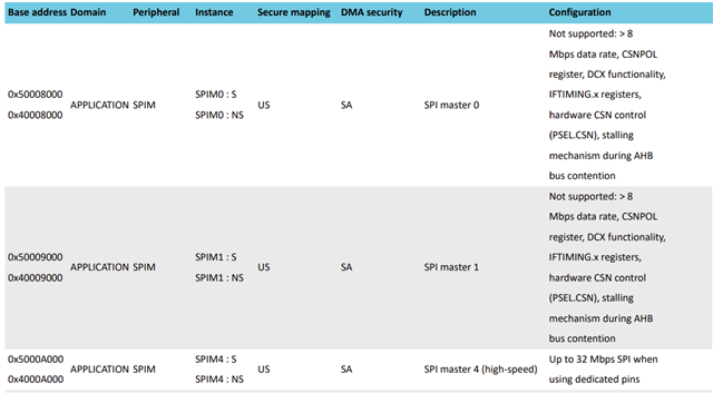
I'm trying to access the nRF5340 over SPI Slave from another processor who is SPI Master. Running a simple "looback test" between an nRF5340 SPI Master and SPI Slave seems to work fine but when I try it with the external processor's SPI Master the data sent on the MOSI line isn't read correctly by the nRF5340  SPI Slave. Taking a snapshot with the Logic analyzer produces some interesting results. The loopback tests I ran is too1/ncs-spi-master-slave-example (github.com) and it works fine (although it does use the deprecated call spi_transeive_async()). However, I notice about a 7 microsecond delay between the SS going low and the SCK transitions. During this time MOSI is idle but MISO toggles 

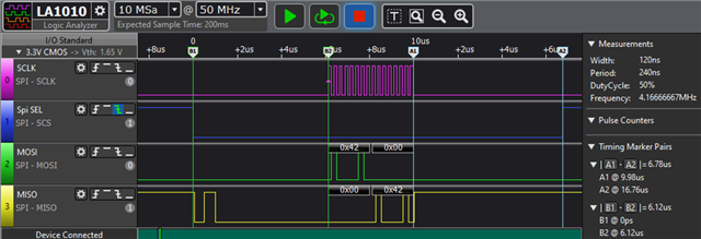
When I try my own SPI Master there's only about 70ns delay between SS and SCK. However, everything is shifted in terms of when SPI Slave starts reading the data. I ran a "walking ones" tests and found that on a 16 bit transfer only bits 7-14 are detected by SPI Slave which reads them as bits 8-15. Also the MISO line still toggles, now being read as 0x3F 0x80

Is there any way to remove this delay requirement? 14usec of wasted time per SPI transaction will create very low transfer rates plus the only way I can perform the delay on the SPI Master side is to replace the SS signal with a GPIO that I toggle manually before making the SPI transfer call.

Here is how I am setting up the SPI Slave port in my device tree overlay file

&pinctrl {
    spi_slave_default: spi_slave_default {
        group1 {
            psels = <NRF_PSEL(SPIS_SCK, 1, 5)>,
                    <NRF_PSEL(SPIS_MOSI, 1, 4)>,
                    <NRF_PSEL(SPIS_MISO, 1, 1)>,
                    <NRF_PSEL(SPIS_CSN, 1, 0)>;
        };
    };

    spi_slave_sleep: spi_slave_sleep {
        group1 {
            psels = <NRF_PSEL(SPIS_SCK, 1, 5)>,
                    <NRF_PSEL(SPIS_MOSI, 1, 4)>,
                    <NRF_PSEL(SPIS_MISO, 1, 1)>,
                    <NRF_PSEL(SPIS_CSN, 1, 0)>;
            low-power-enable;
        };
    };
};
Here is how I'm setting up the SPI config structure:
static const struct spi_config spi_slave_cfg = {
    .operation = SPI_WORD_SET(8)
                 | SPI_TRANSFER_MSB
                 | SPI_MODE_CPHA
                 | SPI_OP_MODE_SLAVE
                 ,
    .frequency = 8000000,
     .slave = 0,
};
These settings match the SPI Master's.
I've tried running the master at 16MHz all the way down to 3.5MHz with the same result.
For the test app, I'm simply using the loopback app above but removing the SPI Master portion.
I"m using ncs version 2.4.2
Parents
  • Hello,

    Yes, there would always be delay after the CS has been enabled till the clock is enabled.

    I have tested it previously and it was ~6u.

    You could send multiple bytes in one transaction and see if it meets your overall requirement.

    Over here:

    .operation = SPI_WORD_SET(8)

    You are setting word size as 8 bit, so what you mean by 16 bit transfers are not detected correctly?

    plus the only way I can perform the delay on the SPI Master side is to replace the SS signal with a GPIO that I toggle manually

    There is a delay parameter in the spi_cs_control struct which is part of the spi_config.

    /BR, Naeem

  • Thank you for your timely response. I'm glad, in a way, to hear that the measured delay I am seeing is expected and not something else I have to diagnose on my side. Your measured ~6us SS-to-SCK delay jibes with my measurements as well. I must say, I've never encountered a part before that adds 12us to every SPI transaction by design.

    >There is a delay parameter in the spi_cs_control struct which is part of the spi_config.

    I have read the documentation on this field here Serial Peripheral Interface (SPI) Bus — Zephyr Project Documentation but it's a bit vague about how to use it and its bounds, etc.  Are you saying that I can use this field to reduce the SPI Slave device SS-to-SCK delay on the nRF5340 to below 6? To 1 or even 0? 

    Could you provide me with an example device tree usage? Since I supplied my device tree entry in the original post if you could show how I might add spi_cs_control to that it would be fantastic.

    Sadly, there is no such control on the SPI Master device side other than using a GPIO instead of the SS line and putting delays between the GPIO control and the SPI. So if there is no way to reduce the latency on your part, we'll need to rethink our design here.

    Thank you for your time.

Reply
  • Thank you for your timely response. I'm glad, in a way, to hear that the measured delay I am seeing is expected and not something else I have to diagnose on my side. Your measured ~6us SS-to-SCK delay jibes with my measurements as well. I must say, I've never encountered a part before that adds 12us to every SPI transaction by design.

    >There is a delay parameter in the spi_cs_control struct which is part of the spi_config.

    I have read the documentation on this field here Serial Peripheral Interface (SPI) Bus — Zephyr Project Documentation but it's a bit vague about how to use it and its bounds, etc.  Are you saying that I can use this field to reduce the SPI Slave device SS-to-SCK delay on the nRF5340 to below 6? To 1 or even 0? 

    Could you provide me with an example device tree usage? Since I supplied my device tree entry in the original post if you could show how I might add spi_cs_control to that it would be fantastic.

    Sadly, there is no such control on the SPI Master device side other than using a GPIO instead of the SS line and putting delays between the GPIO control and the SPI. So if there is no way to reduce the latency on your part, we'll need to rethink our design here.

    Thank you for your time.

Children
  • Hello,

    tozz88 said:
    Your measured ~6us SS-to-SCK delay jibes with my measurements as well. I must say, I've never encountered a part before that adds 12us to every SPI transaction by design.

    Please have a look at this ticket which is pretty much same as your concern, and the suggestion from my colleague to use the SPIM4 instance: Reduce CS to CLK Delay

    tozz88 said:
    Are you saying that I can use this field to reduce the SPI Slave device SS-to-SCK delay

    No, this is a parameter for extra delay if you want to have controlled delay for synchronization etc. As you want lower delay, you should not use it or have set it to 0.

  • Great. Thanks for the information. However, the linked solution sounds like it only works for SPIM4 and I am using SPI Slave, not master. Is there a way to get a similar behavior for SPI Slave?

  • Hello Robert,

    The IFTIMING.x registers are only available on the SPIM4 instance.

    I have few questions here:

    What is your setup? Are you using NRF5340 as a SPI slave? What is your SPI Master? Is it a Nordic Device?

    And what do you mean by this:

    when I try it with the external processor's SPI Master the data sent on the MOSI line isn't read correctly by the nRF5340  SPI Slave.

    What is the CSN to CLK delay you get in this case? (with external master)

    However, I notice about a 7 microsecond delay between the SS going low and the SCK transitions.

    your SPI master should have control on this? right?

    When I try my own SPI Master there's only about 70ns delay between SS and SCK.

    What do you mean here? What is "my own SPI Master" vs "External SPI Master"?

    I would like to understand your overall setup. Will be nice if you could share h/w and code snapshots.

    Regards, Naeem

Related