Unexpected consumption using System OFF Sample & nRF52840DK

Greetings,

I have been measuring the current consumption of our custom FW in our custom board using PPK2 and found some unexpected spikes in the current consumption curve.

I decided to look deeper into this so programmed our custom FW to the nRF52840 DK and the behavior remained the same.

Finally I decide to test some samples with absolutely no changes on the nRF52840DK to confirm the normal behavior of the current curves I should see when the system is Active, in Sleep (system ON Idle) & finally System OFF(which is irrelevant for my application).

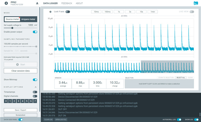
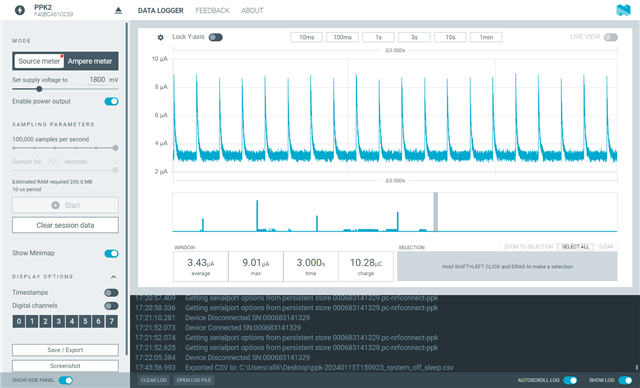
It seems that flashing the nRF System OFF sample (unchanged, as it was in the NCS) to the nRF52840 DK produces the same current curve. As mentioned in other tickets ( I have searched and read all of the relevant ones in existence) the current curve in System Sleep (with UART off) should be a few tens of microamps but I am consistently getting the current curve shown below.

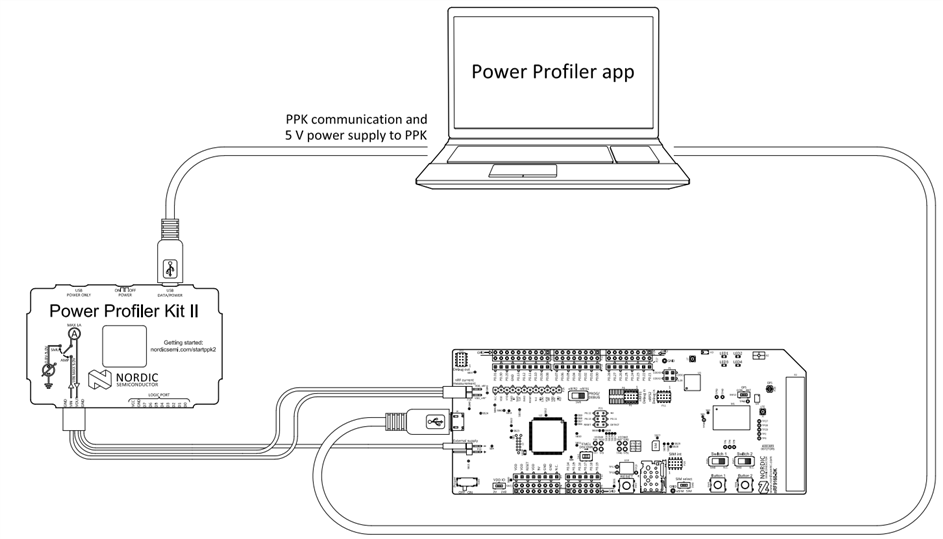
Connection diagram (PPK2 in Ampere mode) 
I have also measured with the SW6 to the DEFAULT and nRF ONLY positions but the results were the same.
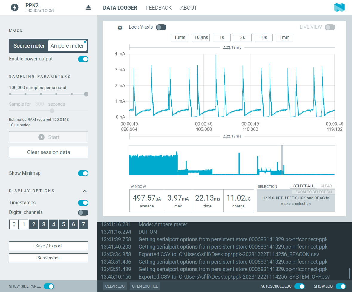
!!!Below you can see the current curve for the nRF52840DK flashed with the nRF System OFF sample and focus on the duration that corresponds to the System Sleep (System ON Idle) part of the duration ( the sample enters the SYstem Sleep state for two seconds, this what is shown below)

System Sleep (System ON Idle)

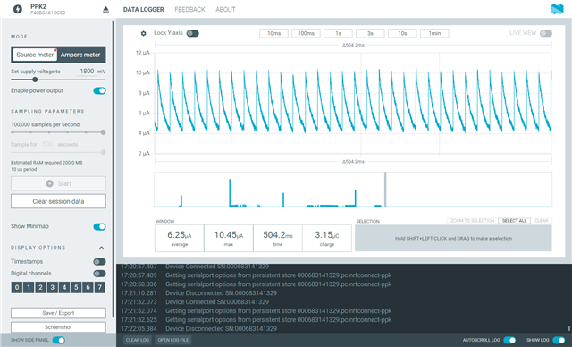
System Sleep (System ON Idle) the curve shown above ZOOMED IN ( to be able to distinguish the spikes)
The whole current curve for the System OFF sample
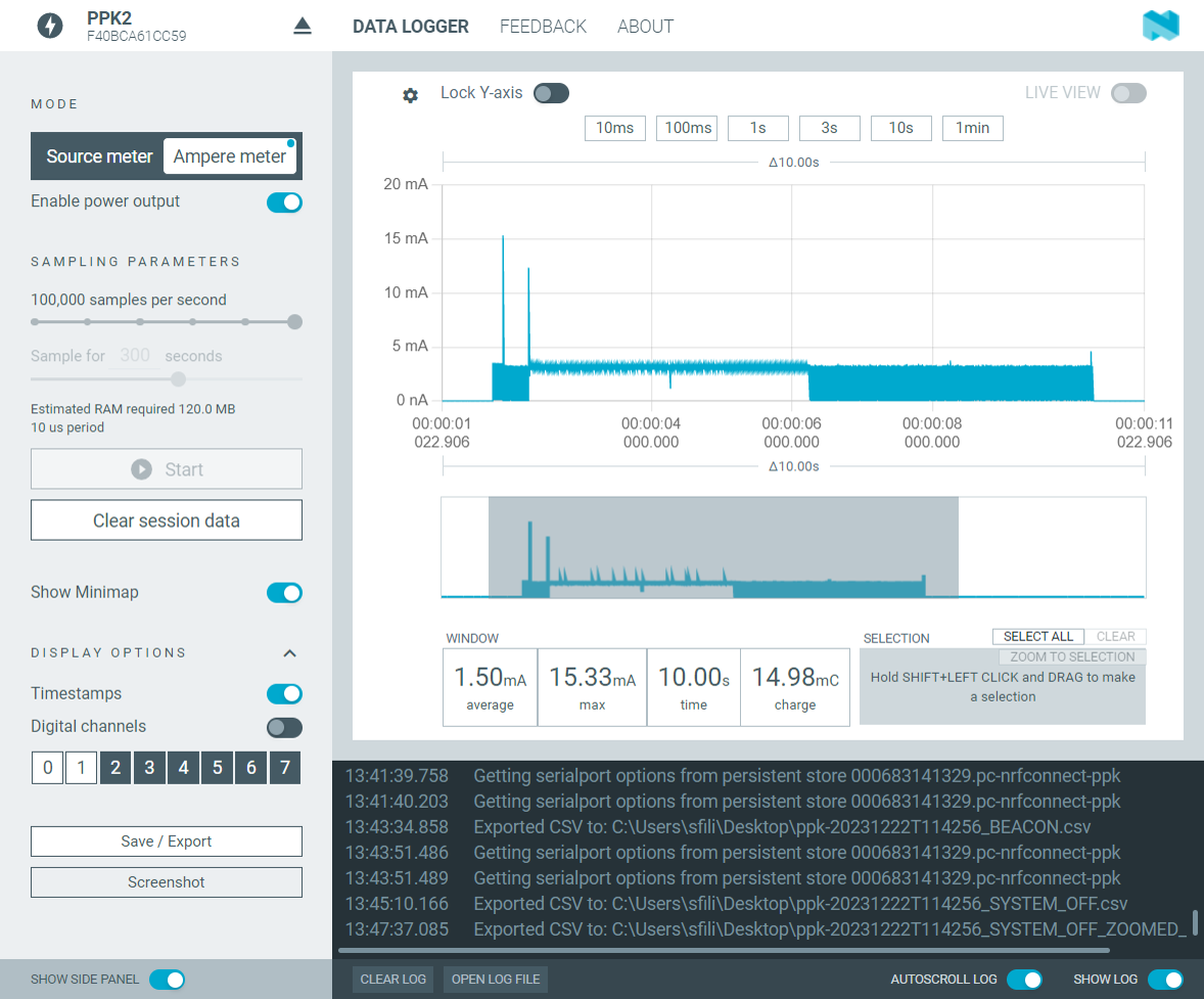
I have tried all different methods of measurement using the PPK2 (Ampere mode & Source mode by providing the external supply from the PPK2) but in all instances, I am getting the same current curve(shown above).

I have also tried the beacon sample (with no changes/modification, as is) and gotten the same curve in Idle mode (apart from when the device wakes up to advertise), between the advertising events I get the same spikes up to 3mA with the current never falling bellow 100's of microamps.

Beacon sample
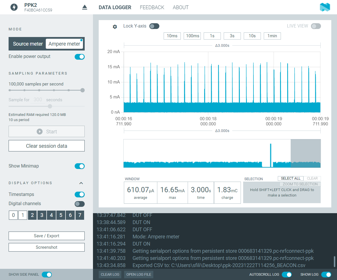
Beacon sample ZOOMED IN
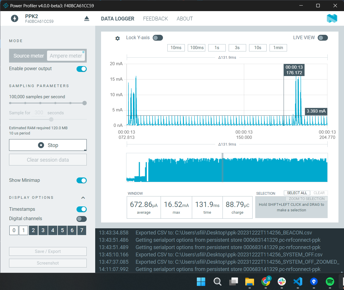
Even more ZOOMED IN
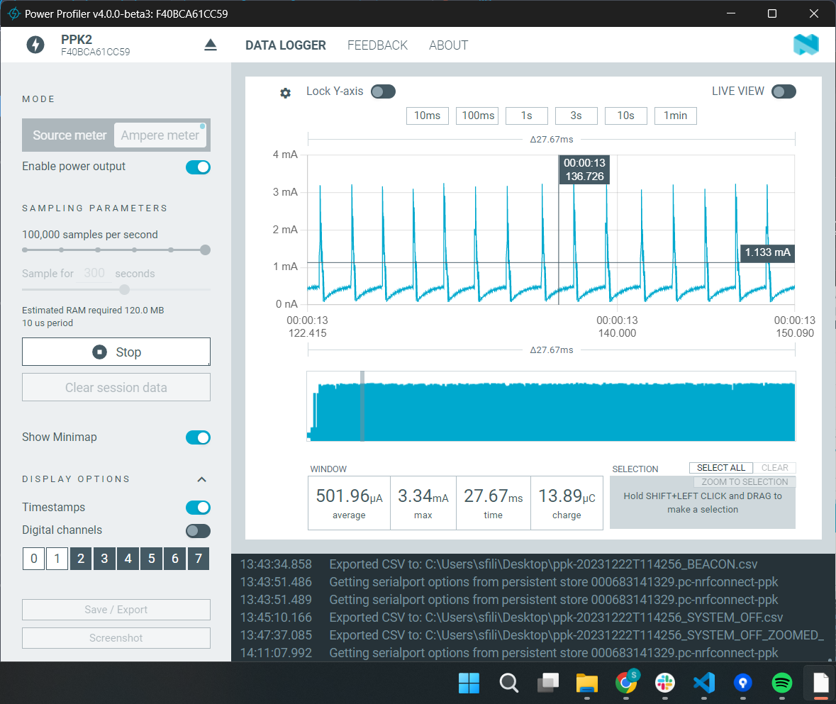
According to other tickets as well as this one that contains current curves for the Beacon sample this is not at all the Normal curve I should see for this sample

(this is what the people in the ticket mentioned report as the normal current curves for this sample)
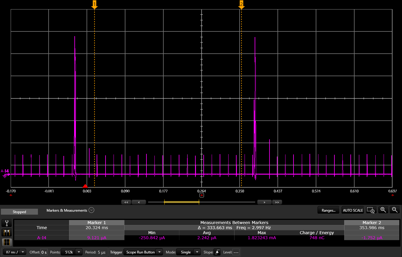
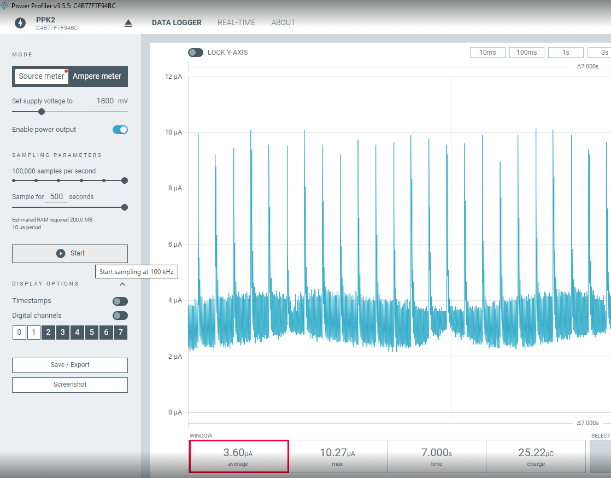
which is completely different from my curves.

What could be the cause for the behavior and current curves I am observing when loading the nRF System OFF & Beacon samples to the nRF52840DK and measuring using the PPK2?

Please get back to me for any further information needed, I can also provide the data for the curves shown above.

I look forward to hearing from you.

Best regards,

Stavros

  • Hi Stravos 

    We are about to enter Christmas vacation on support, so the support will be slow/limted until start of January. 
    Just to verify. Is the DK prepared for current measurement as it is described in the Current measurement guide?

    I would also recommend to not power the DK over USB when you do current measurement as it might affect the measurement. 

    Regards

    Runar

  • Hi runsiv,

    I have followed the exact steps of the Current measurement guide (cut the PCB track shorting solder bridge SB40 etc.)

    I have tried these measurements both with the PPK2 in Ampere Meter mode, connected as mentioned in my previous post, and with the PPK2 in Source Meter mode in which it was connected to the External Supply header (P21) of the DK ( with the P22 shorted with a jumper of course) and the resulting current curve is exactly the same.

    Thank you very much and I am looking forward to hearing from you!

    Best regards,

    Stavros

  • Hi runsiv,

    A kind reminder, for any updates or information about this would be very helpful as this is a critical issue for us.

    I look forward to hearing from you.

    Best regards,

    Stavros

  • Hi Stavros,

    Sorry for the delayed response. Could you please try programming the hex file attached below and measure the current draw on your 52840 DK? Preferably in source mode, as this tends to produce the least amount of noise in the measurements in my experience.

    system_off_demo.hex

    Thanks,

    Vidar

  • Hi Vidar,

    Thank you for your response, I have tried the image you sent on the nRF52840 and measured the power consumption using the PPK2 in source mode and connected to the P21 External Supply header of the nRF52840DK while the SW6 was in the nRF ONLY position.
    The resulting current curve (shown below) has been compared to the nrf system off sample with no modifications at all and it is apparent that the image you sent me corresponds to the nRF52840 entering the System Off mode and not the System Sleep(System ON Idle) which is the mode I am trying to troubleshoot.

    system_off_demo.hex

    system_off (nrf sample unchanged) System Off portion of the current curve


    Unfortunately, the System Off mode is irrelevant to us as we do not use it the issue is with the consumption and current curve found when the sample goes into System Sleep (System ON Idle). Could you please provide feedback for the correct current curve that I should see when the device is in System ON Idle (with UART OFF)?

    Currently using the sample of nrf/system_off I get the following current curve when the device is in System Sleep (System ON Idle).

    Is this correct? Is this what I should see when the device goes into System Sleep (System ON Idle)? 


    Note: all measurements were performed in source mode and connected to the P21 External Supply header of the nRF52840DK while the SW6 was in the nRF ONLY position

    Thank you and I look forward to hearing from you!

    Best regards,

    Stavros

Related