Greetings,
I have been measuring the current consumption of our custom FW in our custom board using PPK2 and found some unexpected spikes in the current consumption curve.
I decided to look deeper into this so programmed our custom FW to the nRF52840 DK and the behavior remained the same.
Finally I decide to test some samples with absolutely no changes on the nRF52840DK to confirm the normal behavior of the current curves I should see when the system is Active, in Sleep (system ON Idle) & finally System OFF(which is irrelevant for my application).
It seems that flashing the nRF System OFF sample (unchanged, as it was in the NCS) to the nRF52840 DK produces the same current curve. As mentioned in other tickets ( I have searched and read all of the relevant ones in existence) the current curve in System Sleep (with UART off) should be a few tens of microamps but I am consistently getting the current curve shown below.
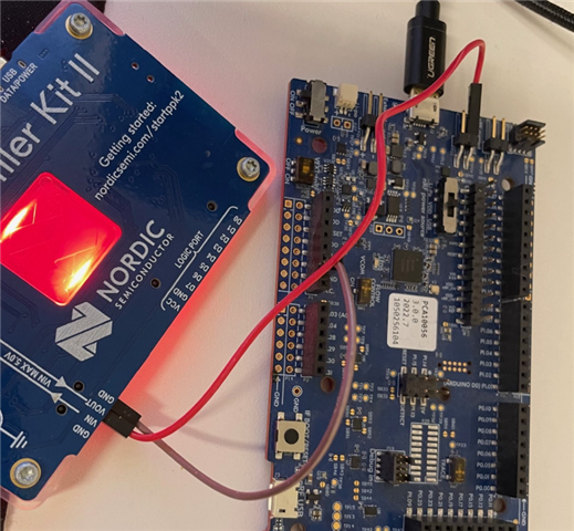
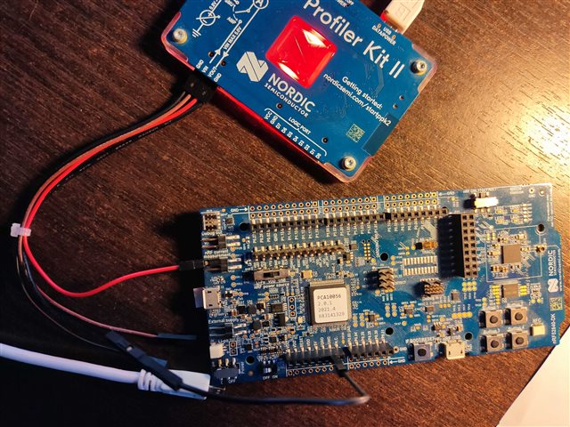
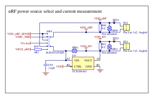
Connection diagram (PPK2 in Ampere mode)
I have also measured with the SW6 to the DEFAULT and nRF ONLY positions but the results were the same.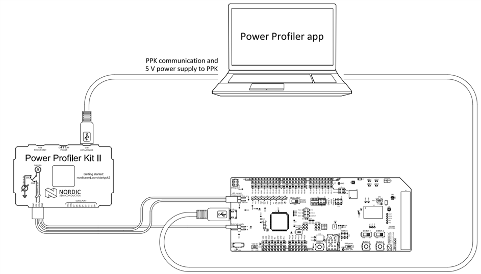
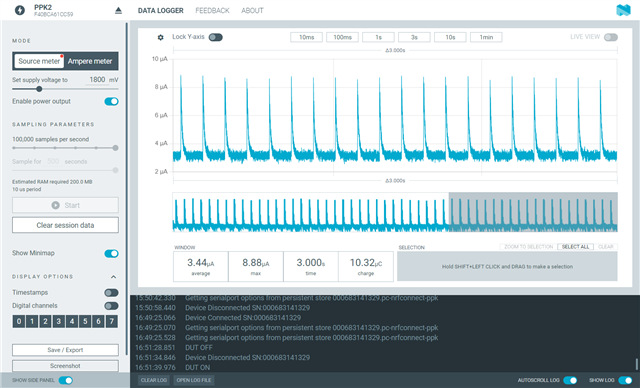
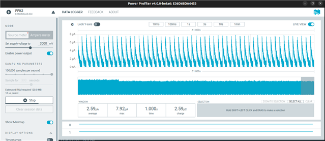
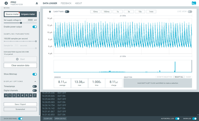
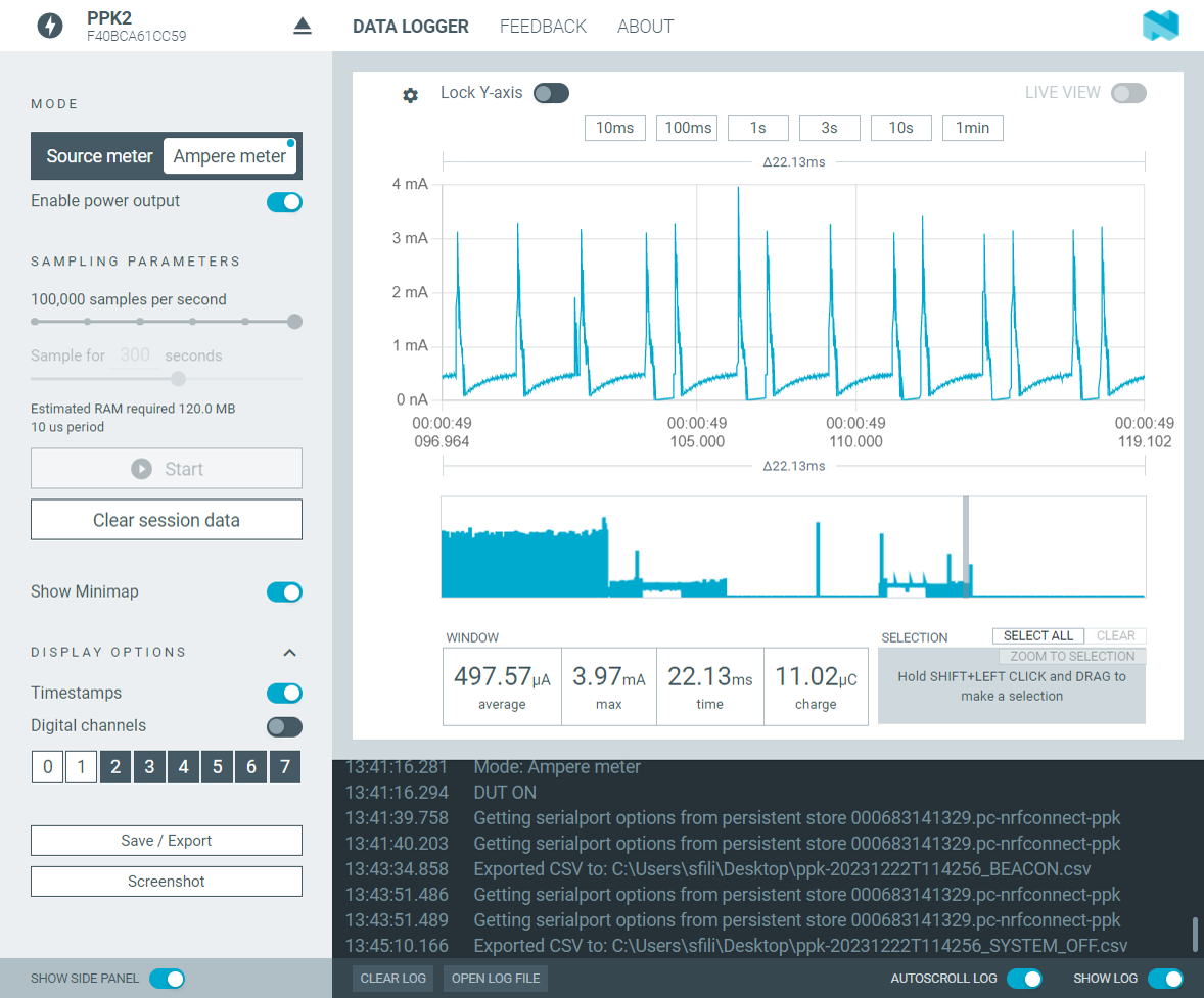
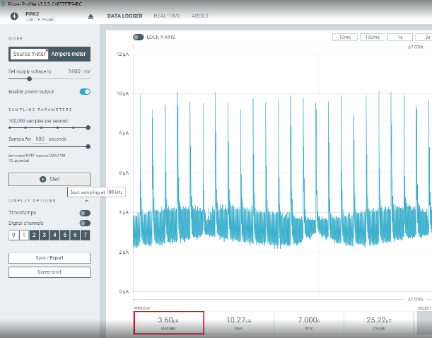
!!!Below you can see the current curve for the nRF52840DK flashed with the nRF System OFF sample and focus on the duration that corresponds to the System Sleep (System ON Idle) part of the duration ( the sample enters the SYstem Sleep state for two seconds, this what is shown below)
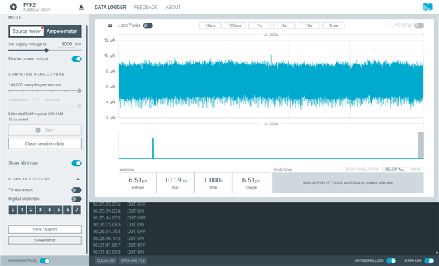
System Sleep (System ON Idle)

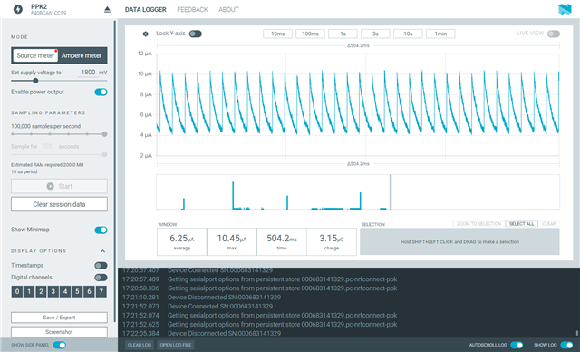
System Sleep (System ON Idle) the curve shown above ZOOMED IN ( to be able to distinguish the spikes)
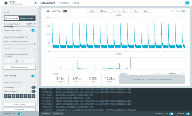
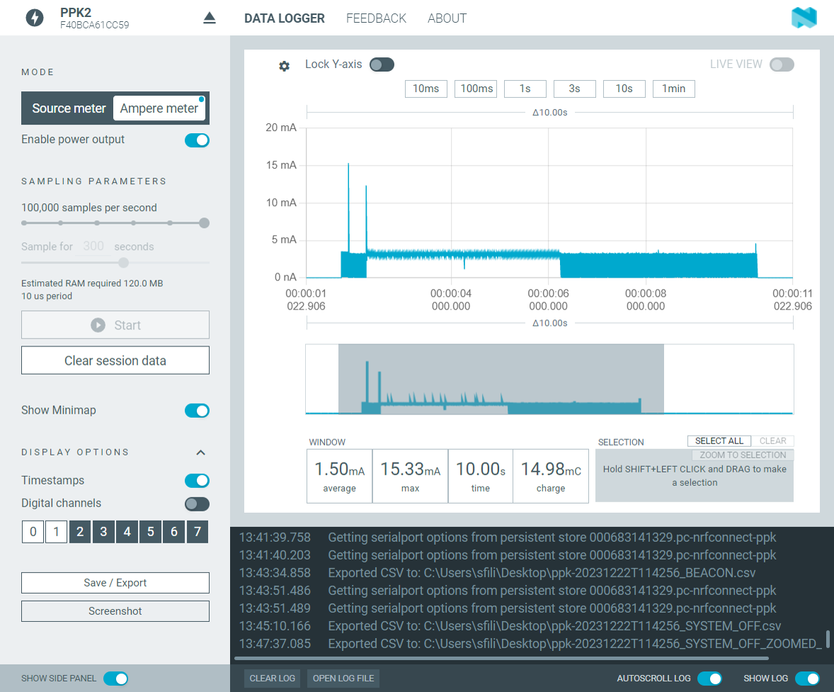
The whole current curve for the System OFF sample
I have tried all different methods of measurement using the PPK2 (Ampere mode & Source mode by providing the external supply from the PPK2) but in all instances, I am getting the same current curve(shown above).
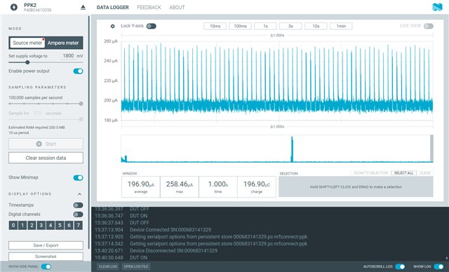
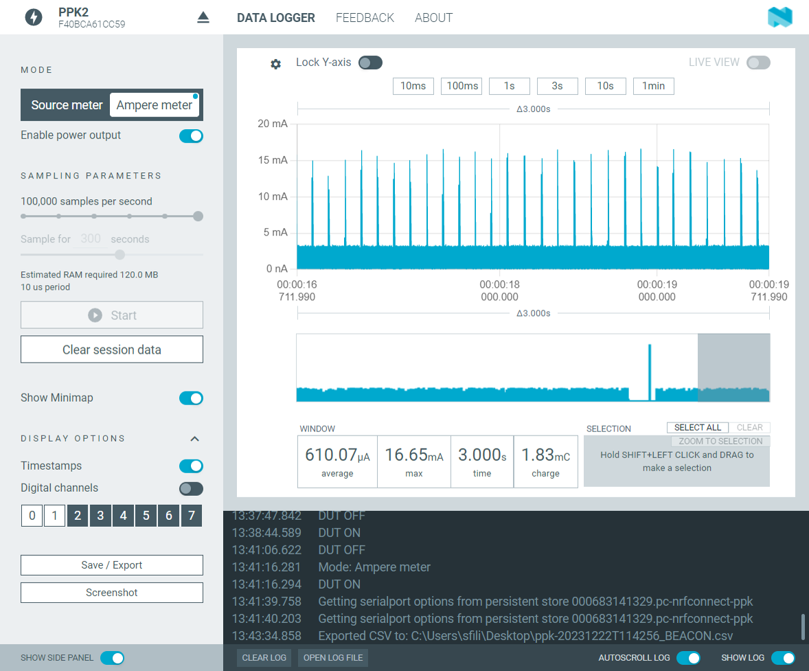
I have also tried the beacon sample (with no changes/modification, as is) and gotten the same curve in Idle mode (apart from when the device wakes up to advertise), between the advertising events I get the same spikes up to 3mA with the current never falling bellow 100's of microamps.
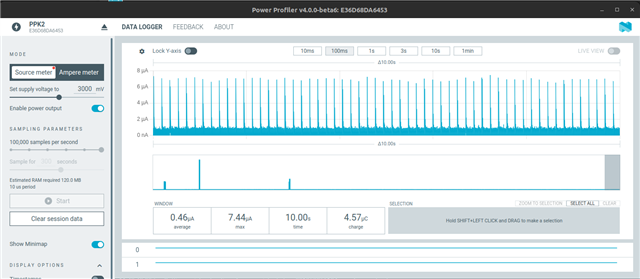
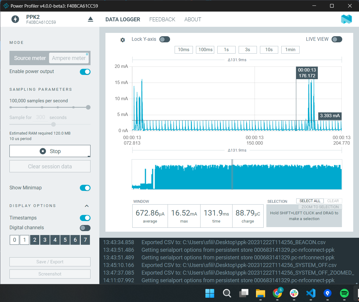
Beacon sample
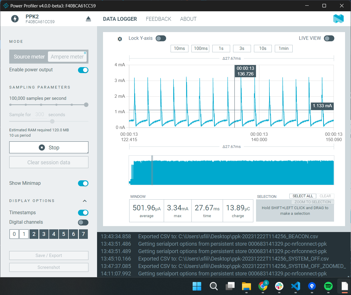
Beacon sample ZOOMED IN
Even more ZOOMED IN
According to other tickets as well as this one that contains current curves for the Beacon sample this is not at all the Normal curve I should see for this sample
(this is what the people in the ticket mentioned report as the normal current curves for this sample)
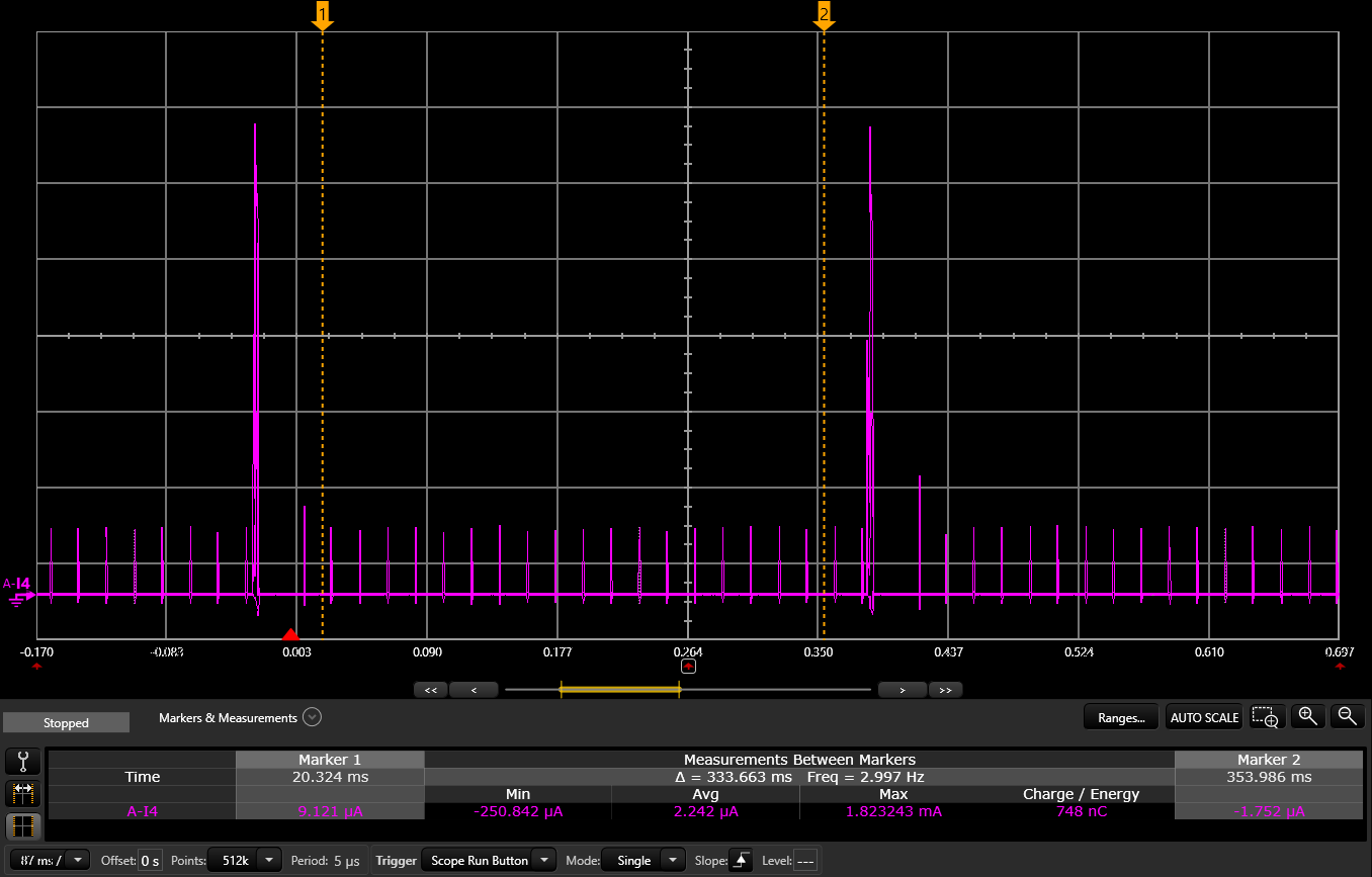
which is completely different from my curves.
What could be the cause for the behavior and current curves I am observing when loading the nRF System OFF & Beacon samples to the nRF52840DK and measuring using the PPK2?
Please get back to me for any further information needed, I can also provide the data for the curves shown above.
I look forward to hearing from you.
Best regards,
Stavros