QSPI clock waveform

Hi

we configured a QSPI application on nRF52840.

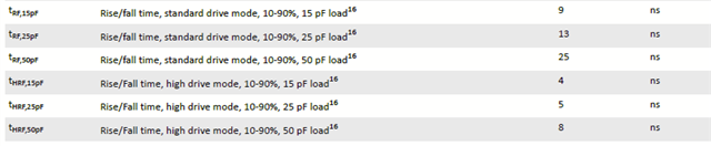
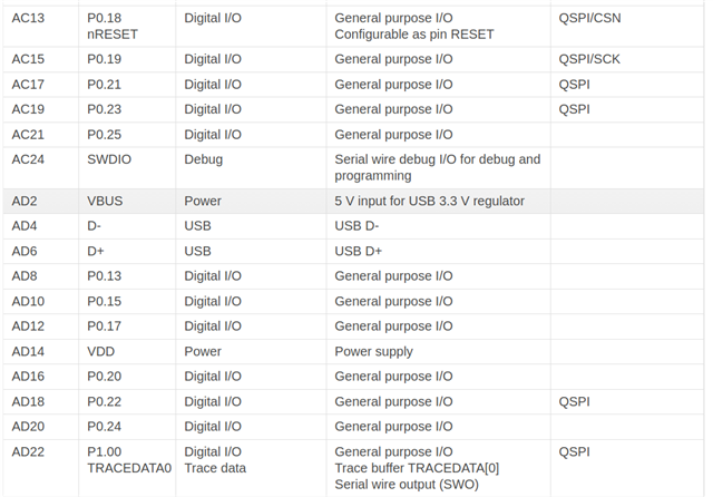
its clock was assigned on p0.04/J1 in hardware design, now we notice that its waveform is close to a square wave as 30MHz maximum, but changes to similar as a sine wave if it is set to 32MHz.

does this mean p0.04 can't be run as such high frequency usage? or only the recommended usage is allowed for QSPI application?

Thanks

Parents Reply
  • Hi,

    Q1: Can you share how the signal looks?

    Q2: How large is the trace from nRF to QSPI-flash?

    P0.04 isn't limited in terms of switching frequency, but QSPI has dedicated recommended pins:


    The overall capacitance, when you probe the pin, will also change. I would recommend that you use a low-capacitance probe to ensure less further loading of the signal. 


    Kind regards,

    Håkon

Children
Related