Error When Compiling I2C Code

Hello,

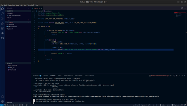
I wrote a sample code to read 8bits from an I2C device as below.

#include <zephyr/kernel.h>
#include <zephyr/drivers/i2c.h>

#define I2C0_NODE DT_NODELABEL(arduino_i2c)

static const struct i2c_dt_spec dev_i2c = I2C_DT_SPEC_GET(I2C0_NODE);

int main(void)
{
        if (!device_is_ready(dev_i2c.bus)) {
	        printk("I2C bus %s is not ready!\n\r",dev_i2c.bus->name);
	        return;
        }

        while(true) {
                uint8_t data;
                int ret = i2c_read_dt(&dev_i2c, &data, sizeof(data));

                if(ret != 0){
	                printk("Failed to read from I2C device address %x.\n", dev_i2c.addr);
                }
                printk("Data %x", data);
        }

        return 0;
}

But I get the following error when I try to compile.

/home/asanka/ncs/v2.5.0/zephyr/include/zephyr/device.h:85:41: error: '__device_dts_ord_DT_N_S_soc_S_peripheral_40000000_S_i2c_9000_BUS_ORD' undeclared here (not in a function); did you mean 'DT_N_S_soc_S_peripheral_40000000_S_i2c_9000_ORD'?
   85 | #define DEVICE_NAME_GET(dev_id) _CONCAT(__device_, dev_id)
      |                                         ^~~~~~~~~
/home/asanka/ncs/v2.5.0/zephyr/include/zephyr/sys/util_internal.h:72:26: note: in definition of macro '__DEBRACKET'
   72 | #define __DEBRACKET(...) __VA_ARGS__
      |                          ^~~~~~~~~~~
/home/asanka/ncs/v2.5.0/zephyr/include/zephyr/sys/util_internal.h:64:9: note: in expansion of macro '__GET_ARG2_DEBRACKET'
   64 |         __GET_ARG2_DEBRACKET(one_or_two_args _if_code, _else_code)
      |         ^~~~~~~~~~~~~~~~~~~~
/home/asanka/ncs/v2.5.0/zephyr/include/zephyr/sys/util_internal.h:59:9: note: in expansion of macro '__COND_CODE'
   59 |         __COND_CODE(_XXXX##_flag, _if_1_code, _else_code)
      |         ^~~~~~~~~~~
/home/asanka/ncs/v2.5.0/zephyr/include/zephyr/sys/util_macro.h:180:9: note: in expansion of macro 'Z_COND_CODE_1'
  180 |         Z_COND_CODE_1(_flag, _if_1_code, _else_code)
      |         ^~~~~~~~~~~~~
/home/asanka/ncs/v2.5.0/zephyr/include/zephyr/drivers/i2c.h:120:17: note: in expansion of macro 'COND_CODE_1'
  120 |                 COND_CODE_1(DT_ON_BUS(node_id, i3c),                    \
      |                 ^~~~~~~~~~~
/home/asanka/ncs/v2.5.0/zephyr/include/zephyr/toolchain/common.h:133:23: note: in expansion of macro '_DO_CONCAT'
  133 | #define _CONCAT(x, y) _DO_CONCAT(x, y)
      |                       ^~~~~~~~~~
/home/asanka/ncs/v2.5.0/zephyr/include/zephyr/device.h:85:33: note: in expansion of macro '_CONCAT'
   85 | #define DEVICE_NAME_GET(dev_id) _CONCAT(__device_, dev_id)
      |                                 ^~~~~~~
/home/asanka/ncs/v2.5.0/zephyr/include/zephyr/device.h:211:37: note: in expansion of macro 'DEVICE_NAME_GET'
  211 | #define DEVICE_DT_NAME_GET(node_id) DEVICE_NAME_GET(Z_DEVICE_DT_DEV_ID(node_id))
      |                                     ^~~~~~~~~~~~~~~
/home/asanka/ncs/v2.5.0/zephyr/include/zephyr/device.h:228:34: note: in expansion of macro 'DEVICE_DT_NAME_GET'
  228 | #define DEVICE_DT_GET(node_id) (&DEVICE_DT_NAME_GET(node_id))
      |                                  ^~~~~~~~~~~~~~~~~~
/home/asanka/ncs/v2.5.0/zephyr/include/zephyr/drivers/i2c.h:105:16: note: in expansion of macro 'DEVICE_DT_GET'
  105 |         .bus = DEVICE_DT_GET(DT_BUS(node_id)),                          \
      |                ^~~~~~~~~~~~~
/home/asanka/ncs/v2.5.0/zephyr/include/zephyr/drivers/i2c.h:122:30: note: in expansion of macro 'I2C_DT_SPEC_GET_ON_I2C'
  122 |                             (I2C_DT_SPEC_GET_ON_I2C(node_id)))          \
      |                              ^~~~~~~~~~~~~~~~~~~~~~
../src/main.c:6:43: note: in expansion of macro 'I2C_DT_SPEC_GET'
    6 | static const struct i2c_dt_spec dev_i2c = I2C_DT_SPEC_GET(I2C0_NODE);
      |                                           ^~~~~~~~~~~~~~~
zephyr/include/generated/devicetree_generated.h:7924:75: warning: unsigned conversion from 'int' to 'short unsigned int' changes value from '1073778688' to '36864' [-Woverflow]
 7924 | #define DT_N_S_soc_S_peripheral_40000000_S_i2c_9000_REG_IDX_0_VAL_ADDRESS 1073778688 /* 0x40009000 */
      |                                                                           ^~~~~~~~~~
/home/asanka/ncs/v2.5.0/zephyr/include/zephyr/sys/util_internal.h:72:26: note: in definition of macro '__DEBRACKET'
   72 | #define __DEBRACKET(...) __VA_ARGS__
      |                          ^~~~~~~~~~~
/home/asanka/ncs/v2.5.0/zephyr/include/zephyr/sys/util_internal.h:64:9: note: in expansion of macro '__GET_ARG2_DEBRACKET'
   64 |         __GET_ARG2_DEBRACKET(one_or_two_args _if_code, _else_code)
      |         ^~~~~~~~~~~~~~~~~~~~
/home/asanka/ncs/v2.5.0/zephyr/include/zephyr/sys/util_internal.h:59:9: note: in expansion of macro '__COND_CODE'
   59 |         __COND_CODE(_XXXX##_flag, _if_1_code, _else_code)
      |         ^~~~~~~~~~~
/home/asanka/ncs/v2.5.0/zephyr/include/zephyr/sys/util_macro.h:180:9: note: in expansion of macro 'Z_COND_CODE_1'
  180 |         Z_COND_CODE_1(_flag, _if_1_code, _else_code)
      |         ^~~~~~~~~~~~~
/home/asanka/ncs/v2.5.0/zephyr/include/zephyr/drivers/i2c.h:120:17: note: in expansion of macro 'COND_CODE_1'
  120 |                 COND_CODE_1(DT_ON_BUS(node_id, i3c),                    \
      |                 ^~~~~~~~~~~
/home/asanka/ncs/v2.5.0/zephyr/include/zephyr/devicetree.h:4233:33: note: in expansion of macro 'DT_N_S_soc_S_peripheral_40000000_S_i2c_9000_REG_IDX_0_VAL_ADDRESS'
 4233 | #define DT_CAT4(a1, a2, a3, a4) a1 ## a2 ## a3 ## a4
      |                                 ^~
/home/asanka/ncs/v2.5.0/zephyr/include/zephyr/devicetree.h:2201:9: note: in expansion of macro 'DT_CAT4'
 2201 |         DT_CAT4(node_id, _REG_IDX_, idx, _VAL_ADDRESS)
      |         ^~~~~~~
/home/asanka/ncs/v2.5.0/zephyr/include/zephyr/devicetree.h:2224:30: note: in expansion of macro 'DT_REG_ADDR_BY_IDX'
 2224 | #define DT_REG_ADDR(node_id) DT_REG_ADDR_BY_IDX(node_id, 0)
      |                              ^~~~~~~~~~~~~~~~~~
/home/asanka/ncs/v2.5.0/zephyr/include/zephyr/drivers/i2c.h:106:17: note: in expansion of macro 'DT_REG_ADDR'
  106 |         .addr = DT_REG_ADDR(node_id)
      |                 ^~~~~~~~~~~
/home/asanka/ncs/v2.5.0/zephyr/include/zephyr/drivers/i2c.h:122:30: note: in expansion of macro 'I2C_DT_SPEC_GET_ON_I2C'
  122 |                             (I2C_DT_SPEC_GET_ON_I2C(node_id)))          \
      |                              ^~~~~~~~~~~~~~~~~~~~~~
../src/main.c:6:43: note: in expansion of macro 'I2C_DT_SPEC_GET'
    6 | static const struct i2c_dt_spec dev_i2c = I2C_DT_SPEC_GET(I2C0_NODE);
      |                                           ^~~~~~~~~~~~~~~
/home/asanka/ncs/v2.5.0/zephyr/include/zephyr/devicetree.h:4229:24: note: in expansion of macro 'DT_N_NODELABEL_arduino_i2c'
 4229 | #define DT_CAT(a1, a2) a1 ## a2
      |                        ^~
/home/asanka/ncs/v2.5.0/zephyr/include/zephyr/devicetree.h:197:29: note: in expansion of macro 'DT_CAT'
  197 | #define DT_NODELABEL(label) DT_CAT(DT_N_NODELABEL_, label)
      |                             ^~~~~~
../src/main.c:4:19: note: in expansion of macro 'DT_NODELABEL'
    4 | #define I2C0_NODE DT_NODELABEL(arduino_i2c)
      |                   ^~~~~~~~~~~~
../src/main.c:6:59: note: in expansion of macro 'I2C0_NODE'
    6 | static const struct i2c_dt_spec dev_i2c = I2C_DT_SPEC_GET(I2C0_NODE);
      |                                                           ^~~~~~~~~
../src/main.c: In function 'main':
../src/main.c:12:17: warning: 'return' with no value, in function returning non-void [-Wreturn-type]
   12 |                 return;
      |                 ^~~~~~
../src/main.c:8:5: note: declared here
    8 | int main(void)
      |     ^~~~

I'm quite new to this platform and I appreciate any help with this. Thank you.

Parents
  • Hi 

    If you are new to Nordic I would strongly check out the Nordic Developer Academy. The introductory course even includes a chapter dedicated to I2C which should help you get started. 

    I expect the problem with your sample is that you haven't created an I2C sensor in your overlay. The I2C_DT_SPEC_GET() macro will not work on the I2C top node itself, you have to use it with one of the sensors (or buses) on the I2C interface. The devacademy chapter will explain this in more detail. 

    Best regards
    Torbjørn

  • Hello,

    Thank you so much. I went through the exercise and implemented I2C and it worked! At least I don't get any errors for now. However, to complete the communication, the other device must receive the chip select pin as LOW. I went ahead and tried to use the GPIO 0.00 to use as a chip select. But the code doesn't continue after:

    gpio_is_ready_dt(&cs)

    I am working on the Make It Matter project and I'm trying to complete my firmware. This is why I didn't yet complete this course as there's only a limited number of days left.

    My code is as follows:

    #include <zephyr/kernel.h>
    #include <zephyr/drivers/i2c.h>
    #include <zephyr/drivers/gpio.h>
    
    #define I2C0_NODE DT_NODELABEL(mysensor)
    #define CS0_NODE DT_NODELABEL(cs0)
    
    static const struct i2c_dt_spec dev_i2c = I2C_DT_SPEC_GET(I2C0_NODE);
    static const struct gpio_dt_spec cs =
    	GPIO_DT_SPEC_GET_OR(DT_NODELABEL(cs0), gpios, {0});
    
    
    int main(void)
    {
            if (!device_is_ready(dev_i2c.bus)) {
    	        printk("I2C bus %s is not ready!\n\r",dev_i2c.bus->name);
    	        return;
            }
    
    	if (!gpio_is_ready_dt(&cs)) {
    		printf("The CS GPIO port is not ready.\n\r");
    		return 0;
    	}
    
            gpio_pin_configure_dt(&cs, GPIO_OUTPUT);
    
            while(true) {
                    uint8_t data;
                    int ret = i2c_read_dt(&dev_i2c, &data, sizeof(data));
    
                    gpio_pin_set_dt(&cs, 0);
    
                    if(ret != 0){
    	                printk("Failed to read from I2C device address %x.\n\r", dev_i2c.addr);
                    } else {
                            printk("Data %x", data);
                    }
    
                    gpio_pin_set_dt(&cs, 1);
            }
    
            return 0;
    }
    

    The overlay file is below:

    &i2c1 {
        compatible = "nordic,nrf-twim";
        status = "okay";
    
        mysensor: mysensor@4a{
            compatible = "i2c-device";
            reg = < 0x4a >;
            label = "MYSENSOR";
        };
    };
    
    &gpio0 {
        compatible = "nordic,nrf-gpio";
        status = "okay";
    
        cs0 {
            gpio-hog;
            gpios = <0 GPIO_ACTIVE_LOW>;
            output-high;
        };
    };

    Any suggestion is highly appreciated.

  • Hi Asanka

    Why would an I2C sensor have a chip select line? 

    Chip select is used by SPI devices, I haven't seen any I2C devices use it. 

    Regardless I don't think your overlay is quite correct. 

    I did something similar in a hobby project of mine, where I needed two output pins that could be manually controlled. 

    You can see the overlay here, and the relevant source here and here.

    Best regards
    Torbjørn 

  • Thank you. This is the device that I'm trying to control. It's an ADC.

    I will take a look at the overlays. I appreciate the support.

  • Hi 

    That looks like an SPI device to me, not an I2C device. If this is the case the I2C interface will struggle to communicate with it, since it will not receive any acknowledge. 

    Best regards
    Torbjørn

  • Hi,

    I think you're right. It seems to be an SPI device. Since it had only CLOCK and DATA, I thought it was I2C. I wrote the code for an SPI device but it doesn't initialize. Can you please let me know what I'm doing wrong?

    The device boots and then prints 'Device not ready...' and reboots.

    Device not ready...*** Booting nRF Connect SDK v2.5.0 ***
    Device not ready...*** Booting nRF Connect SDK v2.5.0 ***
    Device not ready...*** Booting nRF Connect SDK v2.5.0 ***
    Device not ready...*** Booting nRF Connect SDK v2.5.0 ***
    Device not ready...*** Booting nRF Connect SDK v2.5.0 ***
    Device not ready...*** Booting nRF Connect SDK v2.5.0 ***
    Device not ready...*** Booting nRF Connect SDK v2.5.0 ***
    Device not ready...*** Booting nRF Connect SDK v2.5.0 ***
    Device not ready...*** Booting nRF Connect SDK v2.5.0 ***
    Device not ready...*** Booting nRF Connect SDK v2.5.0 ***
    Device not ready...*** Booting nRF Connect SDK v2.5.0 ***
    Device not ready...*** Booting nRF Connect SDK v2.5.0 ***
    Device not ready...

    Code:

    #include <zephyr/kernel.h>
    #include <zephyr/drivers/spi.h>
    
    #define SPI0_NODE DT_NODELABEL(device)
    
    struct spi_cs_control spi_device =
            SPI_CS_CONTROL_INIT(SPI0_NODE, 2);
    
    static const struct spi_dt_spec dev_spi = SPI_CS_GPIOS_DT_SPEC_GET(spi_device);
    
    int main(void)
    {
            while (true) {
                    if (!spi_is_ready_dt(&dev_spi)) {
                            printk("Device not ready....");
                    } else {
                            printk("Device ready....");
                    }
    
                    uint8_t buf;
    
                    spi_read_dt(&dev_spi, &buf);
    
                    printk(" Data %x\n", buf);
            }
            
            return 0;
    }
    

    DT:

    &spi3 {
        compatible = "nordic,nrf-spim";
        status = "okay";
        cs-gpios = <&gpio0 1 GPIO_ACTIVE_HIGH>;
    
        device: device@0 {
            compatible = "spi-device";
            reg = < 0 >;
            spi-max-frequency = < 40000 >;
        };
    };

Reply
  • Hi,

    I think you're right. It seems to be an SPI device. Since it had only CLOCK and DATA, I thought it was I2C. I wrote the code for an SPI device but it doesn't initialize. Can you please let me know what I'm doing wrong?

    The device boots and then prints 'Device not ready...' and reboots.

    Device not ready...*** Booting nRF Connect SDK v2.5.0 ***
    Device not ready...*** Booting nRF Connect SDK v2.5.0 ***
    Device not ready...*** Booting nRF Connect SDK v2.5.0 ***
    Device not ready...*** Booting nRF Connect SDK v2.5.0 ***
    Device not ready...*** Booting nRF Connect SDK v2.5.0 ***
    Device not ready...*** Booting nRF Connect SDK v2.5.0 ***
    Device not ready...*** Booting nRF Connect SDK v2.5.0 ***
    Device not ready...*** Booting nRF Connect SDK v2.5.0 ***
    Device not ready...*** Booting nRF Connect SDK v2.5.0 ***
    Device not ready...*** Booting nRF Connect SDK v2.5.0 ***
    Device not ready...*** Booting nRF Connect SDK v2.5.0 ***
    Device not ready...*** Booting nRF Connect SDK v2.5.0 ***
    Device not ready...

    Code:

    #include <zephyr/kernel.h>
    #include <zephyr/drivers/spi.h>
    
    #define SPI0_NODE DT_NODELABEL(device)
    
    struct spi_cs_control spi_device =
            SPI_CS_CONTROL_INIT(SPI0_NODE, 2);
    
    static const struct spi_dt_spec dev_spi = SPI_CS_GPIOS_DT_SPEC_GET(spi_device);
    
    int main(void)
    {
            while (true) {
                    if (!spi_is_ready_dt(&dev_spi)) {
                            printk("Device not ready....");
                    } else {
                            printk("Device ready....");
                    }
    
                    uint8_t buf;
    
                    spi_read_dt(&dev_spi, &buf);
    
                    printk(" Data %x\n", buf);
            }
            
            return 0;
    }
    

    DT:

    &spi3 {
        compatible = "nordic,nrf-spim";
        status = "okay";
        cs-gpios = <&gpio0 1 GPIO_ACTIVE_HIGH>;
    
        device: device@0 {
            compatible = "spi-device";
            reg = < 0 >;
            spi-max-frequency = < 40000 >;
        };
    };

Children
  • Hello,

    I think I figured it out. I managed to get SPI working after setting up the code as below.

    Read successful. Data: 255
    Read successful. Data: 255
    Read successful. Data: 255
    Read successful. Data: 255

    Code:

    #define SPI0_NODE DT_NODELABEL(device)
    
    const struct spi_config spi_cfg = {
        .frequency = DT_PROP(DT_NODELABEL(spi3), clock_frequency),
        .operation = SPI_OP_MODE_MASTER | SPI_TRANSFER_MSB | SPI_WORD_SET(8),
        .cs = {
            .gpio = {
                .port = DEVICE_DT_GET(DT_SPI_DEV_CS_GPIOS_CTLR(DT_NODELABEL(device))),
                .pin = DT_SPI_DEV_CS_GPIOS_PIN(DT_NODELABEL(device)),
                .dt_flags = DT_SPI_DEV_CS_GPIOS_FLAGS(DT_NODELABEL(device)),
            },
            .delay = 400,
        },
    };


    int main(void)
    {
        const struct device *dev_spi;
        dev_spi = DEVICE_DT_GET(DT_NODELABEL(spi3));
    
        if (!device_is_ready(dev_spi)) {
            printk("Device not ready....");
        } else {
            printk("Device ready....");
        }
    
        printk("\n");
    
        while (true) {
            uint8_t x = 0;
    
            struct spi_buf rx_bufs = { &x, 8 };
            struct spi_buf_set rx = { &rx_bufs, 1 };
    
            //gpio_pin_set_dt(&spi_cfg.cs.gpio, 0);
    
            uint8_t status = spi_read(dev_spi, &spi_cfg, &rx);
    
            //gpio_pin_set_dt(&spi_cfg.cs.gpio, 1);
    
            if (status == 0) {
                printk("Read successful. Data: %d", x);
            } else {
                printk("Read failed. Status: %x", status);
            }
    
            printk("\n");
    
            k_sleep(K_MSEC(1000));
        }
        
        return 0;
    }

    DT:

    &spi3 {
        compatible = "nordic,nrf-spim";
        status = "okay";
        cs-gpios = < &gpio1 1 (GPIO_ACTIVE_HIGH || GPIO_OPEN_DRAIN) >;
        clock-frequency = < 10000000 >;
    
        device: device@0 {
            compatible = "spi-device";
            reg = < 0 >;
            spi-max-frequency = < 20000000 >;
        };
    };

    The sensor seems to be not working because there's a damaged terminal. However, the ADC that I've used seem to be communicating correctly.

    In the case of GPIO, strangely enough, I figured out that only several GPIOs can be used for IO purposes. I am not sure what the reason for this is and there doesn't seem to be a pattern. This is the code for it.

    Code:

    #include <zephyr/kernel.h>
    #include <zephyr/drivers/gpio.h>
    
    #define INDICATOR_LED_NODE DT_NODELABEL(indicator_led)
    
    #define INITIALIZE_TIMEOUT 1
    
    static const struct gpio_dt_spec pin_led = GPIO_DT_SPEC_GET(INDICATOR_LED_NODE, gpios);
    
    int main(void)
    {
            printk("Initializing hardware...\n");
            initialize();
    
            gpio_pin_set_dt(&pin_engage, 1);
    
            printk("Enabled.\nRunning.");
    
            while (true)
            {
                    printk(".");
                    gpio_pin_toggle_dt(&pin_led);
                    k_sleep(K_MSEC(1000));
                    gpio_pin_toggle_dt(&pin_led);
                    k_sleep(K_SECONDS(1));
            }
            
    
            return 0;
    }
    
    void initialize() {
            int error_flag = 0;
    
            do {
                    error_flag += initialize_device(pin_led, GPIO_OUTPUT);
    
                    if (error_flag != 0) {
                            printk("One or more devices could not be initialized. Will retry in %d seconds...\n", INITIALIZE_TIMEOUT);
                            k_sleep(K_MSEC(INITIALIZE_TIMEOUT * 1000));
                            error_flag = 0;
                    } else {
                            printk("Hardware initialized.\n");
                    }
            } while (error_flag != 0);
    }
    
    int initialize_device(const struct gpio_dt_spec device, gpio_flags_t flags) {
    	if(!device_is_ready(device.port)) {
                    printk("ERROR: %s could not be initialized. Device is not ready.", device.port->name);
    
    		return -1;
    	}
    
            int ret = gpio_pin_configure_dt(&device, flags);
    	if (ret) {
                    printk("ERROR: %s could not be initialized. Pin configuration failed.", device.port->name);
    
    		return -2;
    	}
    
            return 0;
    }

    DT:

    /{
    	board_interface {
    		compatible = "gpio-leds";
    
    		indicator_led: indicator_led {
    			gpios = <&gpio0 26 (GPIO_OPEN_DRAIN)>;
    			label = "Control indicator LED";
    		};
    	};
    };

    The traces are pulled up on the PCB itself so it should be an open drain or push-pull from the microcontroller. Only a handful of available GPIOs respond when I try to control them. Maybe you can suggest a reason why this is happening? Thanks for the support! Couldn't have done it without your code and suggestions.

  • Hi

    If you only read 255 (b11111111) it does point to some communication or sensor issue, as this probably means the MISO line is constantly high, rather than receiving actual data. 

    Asanka said:
    Only a handful of available GPIOs respond when I try to control them. Maybe you can suggest a reason why this is happening?

    The nRF5340 chip on the nRF7002DK uses a lot of GPIO's for connecting the nRF7002, external flash memory, buttons, LED's and other things. Possibly the GPIO's you are unable to control are already assigned to some of these other functions? 

    You can get a visual representation of your board file in VSCode which shows you at a glance what the various IO pins are assigned to. Not sure you have tried this out? 

    It should look something like this:

    Best regards
    Torbjørn

Related