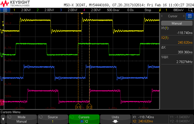
Start PWMs synchronous

Hello there,

I have configured the 4 PWM peripherals to generate a certain waveform. I need to start all 4 pwm peripherals simultaneous.

I thought of achieving this through usage of the PPI + EGU.
EGU channel 0 event triggers EGU channel 1 and channel 2 tasks.

EGU channel 1 event triggers PWM0/1 SEQSTART tasks.

EGU channel 2 event triggers PWM2/3 SEQSTART tasks.

This is written in the code below:

static void setup_ppi(nrf_ppi_channel_t *channel, uint32_t event, uint32_t task1, uint32_t task2)
{
    nrfx_err_t err = nrfx_ppi_channel_alloc(channel);
    assert(err == NRFX_SUCCESS);
    err = nrfx_ppi_channel_assign(*channel, event, task1);
    assert(err == NRFX_SUCCESS);
    err = nrfx_ppi_channel_fork_assign(*channel, task2);
    assert(err == NRFX_SUCCESS);
    err = nrfx_ppi_channel_enable(*channel);
    assert(err == NRFX_SUCCESS);
}

static void start_pwms(const nrfx_pwm_t *pwms)
{
    nrf_ppi_channel_t channel[3];

    setup_ppi(&channel[0], nrf_egu_event_address_get(NRF_EGU0, NRF_EGU_EVENT_TRIGGERED0),
              nrf_egu_task_address_get(NRF_EGU0, NRF_EGU_TASK_TRIGGER1),
              nrf_egu_task_address_get(NRF_EGU0, NRF_EGU_TASK_TRIGGER2));
    setup_ppi(&channel[1], nrf_egu_event_address_get(NRF_EGU0, NRF_EGU_EVENT_TRIGGERED1),
              nrfx_pwm_task_address_get(&pwms[0], NRF_PWM_TASK_SEQSTART1),
              nrfx_pwm_task_address_get(&pwms[1], NRF_PWM_TASK_SEQSTART1));
    setup_ppi(&channel[2], nrf_egu_event_address_get(NRF_EGU0, NRF_EGU_EVENT_TRIGGERED2),
              nrfx_pwm_task_address_get(&pwms[2], NRF_PWM_TASK_SEQSTART1),
              nrfx_pwm_task_address_get(&pwms[3], NRF_PWM_TASK_SEQSTART1));

    nrf_egu_task_trigger(NRF_EGU0, NRF_EGU_TASK_TRIGGER0);

    for (size_t k = 0; k < ARRAY_SIZE(channel); k++) {
        nrfx_err_t err = nrfx_ppi_channel_free(channel[k]);
        assert(NRFX_SUCCESS == err);
    }
}

The following 4 signals should rise at the same time, however they are 1.85 us out of sync.


Triggering the PWM SEQSTART tasks manually has the same result:

    nrf_pwm_task_trigger(NRF_PWM0, NRF_PWM_TASK_SEQSTART1);
    nrf_pwm_task_trigger(NRF_PWM1, NRF_PWM_TASK_SEQSTART1);
    nrf_pwm_task_trigger(NRF_PWM2, NRF_PWM_TASK_SEQSTART1);
    nrf_pwm_task_trigger(NRF_PWM3, NRF_PWM_TASK_SEQSTART1);

Strangely enough, if I reverse the order in which I start the PWMS:

    nrf_pwm_task_trigger(NRF_PWM3, NRF_PWM_TASK_SEQSTART1);
    nrf_pwm_task_trigger(NRF_PWM2, NRF_PWM_TASK_SEQSTART1);
    nrf_pwm_task_trigger(NRF_PWM1, NRF_PWM_TASK_SEQSTART1);
    nrf_pwm_task_trigger(NRF_PWM0, NRF_PWM_TASK_SEQSTART1);

The PWM signals are still generated in order PWM0->PWM3


Can anyone explain this? Is there no way to start the PWMs at the same time?

I am using NCS V2.5.0.

Parents
  • Hi!

    Do you have different duty cycles on these 4 signals? It could be that they started at the same time, but what you see is just a offset due to different duty cycles?

    If this is not the case, then please provide more info about how you have configured the PWM sequences. A example that reproduces the issue would be helpful.

  • I have configured the same duty cycle (0xFFFF).
    I have included a snippet below. The actual code makes a more elaborate pattern, but I removed that for simplicity.

    #include "pwm_controller.h"
    
    #include <zephyr/kernel.h>
    #include <assert.h>
    
    #include <nrfx_pwm.h>
    #include <nrfx_ppi.h>
    #include <nrfx_egu.h>
    
    #define NUM_AVAIL_PWMS 4
    #define NRFX_PWM_PIN_NOT_USED (0xff)
    
    typedef struct {
        nrf_pwm_values_wave_form_t pwm_values[NUM_AVAIL_PWMS][STIMENGINE_PATTERN_STEPS_MAX];
        struct k_event event_done;
    } pwm_controller_data_t;
    
    typedef struct {
        nrfx_pwm_t pwm_instance[NUM_AVAIL_PWMS];
    } pwm_controller_cfg_t;
    
    static pwm_controller_data_t pwm_controller_data;
    static pwm_controller_cfg_t pwm_controller_config = {
        .pwm_instance = { NRFX_PWM_INSTANCE(0), NRFX_PWM_INSTANCE(1), NRFX_PWM_INSTANCE(2), NRFX_PWM_INSTANCE(3), },
    };
    
    void pwm_controller_init(void)
    {
        IRQ_DIRECT_CONNECT(PWM0_IRQn, 0, nrfx_pwm_0_irq_handler, 0);
        IRQ_DIRECT_CONNECT(PWM1_IRQn, 0, nrfx_pwm_1_irq_handler, 0);
        IRQ_DIRECT_CONNECT(PWM2_IRQn, 0, nrfx_pwm_2_irq_handler, 0);
        IRQ_DIRECT_CONNECT(PWM3_IRQn, 0, nrfx_pwm_3_irq_handler, 0);
    }
    
    static uint16_t bool_to_pwm(bool high)
    {
        return high ? 0xFFFF : 0x7FFF;
    }
    
    static void generate_pattern(pwm_controller_data_t *data)
    {
        const bool pattern[4][3] = {
            { true, false, false },
            { false, true, false },
            { true, false, true },
            { false, false, false },
        };
        const uint16_t timing_us[4] = { 10, 50, 10, 5 };
        for (int step = 0; step < 4; step++) {
            for (int pwm = 0; pwm < NUM_AVAIL_PWMS; pwm++) {
                data->pwm_values[pwm][step].channel_0 = bool_to_pwm(pattern[step][0]);
                data->pwm_values[pwm][step].channel_1 = bool_to_pwm(pattern[step][1]);
                data->pwm_values[pwm][step].channel_2 = bool_to_pwm(pattern[step][2]);
                data->pwm_values[pwm][step].counter_top = timing_us[step];
            }
        };
    }
    
    static void pwm_handler(nrfx_pwm_evt_type_t event_type, void *ctx)
    {
        if (event_type != NRFX_PWM_EVT_FINISHED) {
            return;
        }
        const nrfx_pwm_t *pwm = (const nrfx_pwm_t *) ctx;
        k_event_set(&(pwm_controller_data.event_done), (1 << pwm->instance_id));
    }
    
    static void prepare_pwms(const nrfx_pwm_t *pwm, nrf_pwm_values_wave_form_t *wave, const uint8_t *pins,
                             size_t wave_form_len)
    {
        const nrfx_pwm_config_t pwm_config = {
                .output_pins = {
                    pins[0],
                    pins[1],
                    pins[2],
                    NRFX_PWM_PIN_NOT_USED,
                },
                .pin_inverted = {false, false, false, false},
                .irq_priority = 4,
                .base_clock = NRF_PWM_CLK_1MHz,
                .count_mode = NRF_PWM_MODE_UP,
                .top_value = 0,
                .load_mode = NRF_PWM_LOAD_WAVE_FORM,
                .step_mode = NRF_PWM_STEP_AUTO,
                .skip_gpio_cfg = false,
                .skip_psel_cfg = false,
            };
        const nrfx_err_t err = nrfx_pwm_init(pwm, &pwm_config, pwm_handler, (void *) pwm);
        assert(NRFX_SUCCESS == err);
        const uint32_t flags = NRFX_PWM_FLAG_START_VIA_TASK | NRFX_PWM_FLAG_STOP;
        const nrf_pwm_sequence_t seq = {
            .values.p_wave_form = wave,
            .length = 4 * wave_form_len,
            .repeats = 0,
            .end_delay = 0,
        };
        nrfx_pwm_simple_playback(pwm, &seq, 1, flags);
    }
    
    static void setup_ppi(nrf_ppi_channel_t *channel, uint32_t event, uint32_t task1, uint32_t task2)
    {
        nrfx_err_t err = nrfx_ppi_channel_alloc(channel);
        assert(err == NRFX_SUCCESS);
        err = nrfx_ppi_channel_assign(*channel, event, task2);
        assert(err == NRFX_SUCCESS);
        err = nrfx_ppi_channel_fork_assign(*channel, task1);
        assert(err == NRFX_SUCCESS);
        err = nrfx_ppi_channel_enable(*channel);
        assert(err == NRFX_SUCCESS);
    }
    
    static void start_pwms(const nrfx_pwm_t *pwms)
    {
        nrf_ppi_channel_t channel[3];
    
        setup_ppi(&channel[0], nrf_egu_event_address_get(NRF_EGU0, NRF_EGU_EVENT_TRIGGERED0),
                  nrf_egu_task_address_get(NRF_EGU0, NRF_EGU_TASK_TRIGGER1),
                  nrf_egu_task_address_get(NRF_EGU0, NRF_EGU_TASK_TRIGGER2));
        setup_ppi(&channel[1], nrf_egu_event_address_get(NRF_EGU0, NRF_EGU_EVENT_TRIGGERED1),
                  nrfx_pwm_task_address_get(&pwms[0], NRF_PWM_TASK_SEQSTART1),
                  nrfx_pwm_task_address_get(&pwms[1], NRF_PWM_TASK_SEQSTART1));
        setup_ppi(&channel[2], nrf_egu_event_address_get(NRF_EGU0, NRF_EGU_EVENT_TRIGGERED2),
                  nrfx_pwm_task_address_get(&pwms[2], NRF_PWM_TASK_SEQSTART1),
                  nrfx_pwm_task_address_get(&pwms[3], NRF_PWM_TASK_SEQSTART1));
    
        nrf_egu_task_trigger(NRF_EGU0, NRF_EGU_TASK_TRIGGER0);
    
        for (size_t k = 0; k < ARRAY_SIZE(channel); k++) {
            nrfx_err_t err = nrfx_ppi_channel_free(channel[k]);
            assert(NRFX_SUCCESS == err);
        }
    }
    
    void pwm_controller_generate(void)
    
    {
        const pwm_controller_cfg_t *p_cfg = &pwm_controller_config;
        pwm_controller_data_t *p_data = &pwm_controller_data;
    
        generate_pattern(p_data);
    
        const uint8_t pins[12] = {
            13, 19, 25, 10, 5 + 32, 3 + 32, 9 + 32, 11, 1 + 32, 4 + 32, 28, 0xff,
        };
    
        for (int pwm = 0; pwm < NUM_AVAIL_PWMS; pwm++) {
            prepare_pwms(&p_cfg->pwm_instance[pwm], p_data->pwm_values[pwm], &pins[3 * pwm], 4);
        }
    
        start_pwms(p_cfg->pwm_instance);
    
        uint32_t events = k_event_wait(&(p_data->event_done), 0xF, true, K_FOREVER);
        if (events == 0) {
            printk("timeout\n");
        }
        for (size_t k = 0; k < NUM_AVAIL_PWMS; k++) {
            nrfx_pwm_uninit(&(p_cfg->pwm_instance[k]));
        }
    }
    

  • This was measured with an InfiniVision MSO-X 3024T (200 MHz, 5GSa/s).
    I also changed the signals to high-drive (but this did not seem change much) :/

  • I agree with your findings, and have the tested fix which I post here. Interestingly my testing on the nRF52832 does not show this behaviour, it only seems to happen on the nRF52833 and would have impacted my current project which happens to be replacing the nRF52832 with the nRF52833 so thanks for raising this :-)

    The cause is in this mode each PWM reads data on start from RAM using DMA via the AHB bus network; each PWM is a Bus Master, and RAM is a group of Bus Slaves. Priority of the Bus Masters is PWM0/PWM1/PWM2/PWM3 which explains one of your earlier comments.

    These are my notes on AHB Bus Masters:

    // nRF52833 Bus Masters
    // ====================
    // Each bus master is connected to all the slave devices using an interconnection matrix. The bus masters are
    // assigned priorities, which are used to resolve access when two (or more) bus masters request access to
    // the same slave device. When that occurs, the following rules apply:
    // - If two (or more) bus masters request access to the same slave device, the master with the highest
    // priority is granted the access first.
    // - Bus masters with lower priority are stalled until the higher priority master has completed its transaction.
    // To avoid AHB bus contention when using multiple bus masters, follow
    // these guidelines:
    // - Avoid situations where more than one bus master is accessing the same slave.
    // - If more than one bus master is accessing the same slave, make sure that the bus bandwidth is not exhausted.
    // Below is a list of bus masters in the system and their priorities.
    //  PWM0
    //  PWM1
    //  PWM2
    //  PWM3
    

    To avoid a 2-cycle 16MHz stall on the Bus Masters, the 4 x PWM cannot share the same AHB Bus Slave, and RAM is a Bus Slave:

    //           Name  AdrSpace    StartAdr    EndAdr      AccType
    // Memory =  RAM0  Memory      0x20000000  0x20001FFF  RW
    // Memory =  RAM1  Memory      0x20002000  0x20003FFF  RW
    // Memory =  RAM2  Memory      0x20004000  0x20005FFF  RW
    // Memory =  RAM3  Memory      0x20006000  0x20007FFF  RW
    // Memory =  RAM4  Memory      0x20008000  0x20009FFF  RW
    // Memory =  RAM5  Memory      0x2000A000  0x2000BFFF  RW
    // Memory =  RAM6  Memory      0x2000C000  0x2000DFFF  RW
    // Memory =  RAM7  Memory      0x2000E000  0x2000FFFF  RW
    // Memory =  RAM8  Memory      0x20010000  0x2001FFFF  RW

    The fix is to allocate a separate RAM Slave for each PWM; a nuisance, but it works.

    #define SEQUENCE_SIZE  2
    #pragma location = 0x20006000
    static  uint16_t pwm_seq_0[SEQUENCE_SIZE] = {PWM_CH0_DUTY, PWM_CH1_DUTY};
    #pragma location = 0x20008000
    static  uint16_t pwm_seq_1[SEQUENCE_SIZE] = {PWM_CH0_DUTY, PWM_CH1_DUTY};
    #pragma location = 0x2000A000
    static  uint16_t pwm_seq_2[SEQUENCE_SIZE] = {PWM_CH0_DUTY, PWM_CH1_DUTY};
    #pragma location = 0x2000C000
    static  uint16_t pwm_seq_3[SEQUENCE_SIZE] = {PWM_CH0_DUTY, PWM_CH1_DUTY};
    // Map file output after compile:
    // pwm_seq_0               0x2000'6000    0x4  Data  Lc  main.o [1]
    // pwm_seq_1               0x2000'8000    0x4  Data  Lc  main.o [1]
    // pwm_seq_2               0x2000'a000    0x4  Data  Lc  main.o [1]
    // pwm_seq_3               0x2000'c000    0x4  Data  Lc  main.o [1]

    Full tested code with no phase offset on nRF52833; PWM pins are using nRF52833 DK LEDs which load the waveform for a better test. IAR compiler but SES is similar:

    #define PWM_CH0_DUTY 8                      // 50% duty cycle
    #define PWM_CH1_DUTY PWM_CH0_DUTY | (1<<15) // 50% duty cycle, polarity bit set so inverse of CH0
    static void EnableExtClockPWM(NRF_PWM_Type * const pPWM, const uint32_t PWM_Pin, const uint16_t * const pSequence);
    
    // nRF52833 Bus Masters
    // ====================
    // Each bus master is connected to all the slave devices using an interconnection matrix. The bus masters are
    // assigned priorities, which are used to resolve access when two (or more) bus masters request access to
    // the same slave device. When that occurs, the following rules apply:
    // - If two (or more) bus masters request access to the same slave device, the master with the highest
    // priority is granted the access first.
    // - Bus masters with lower priority are stalled until the higher priority master has completed its transaction.
    // To avoid AHB bus contention when using multiple bus masters, follow
    // these guidelines:
    // - Avoid situations where more than one bus master is accessing the same slave.
    // - If more than one bus master is accessing the same slave, make sure that the bus bandwidth is not exhausted.
    // Below is a list of bus masters in the system and their priorities.
    // PWM0
    // PWM1
    // PWM2
    // PWM3
    //           Name  AdrSpace    StartAdr    EndAdr      AccType
    // Memory =  RAM0  Memory      0x20000000  0x20001FFF  RW
    // Memory =  RAM1  Memory      0x20002000  0x20003FFF  RW
    // Memory =  RAM2  Memory      0x20004000  0x20005FFF  RW
    // Memory =  RAM3  Memory      0x20006000  0x20007FFF  RW
    // Memory =  RAM4  Memory      0x20008000  0x20009FFF  RW
    // Memory =  RAM5  Memory      0x2000A000  0x2000BFFF  RW
    // Memory =  RAM6  Memory      0x2000C000  0x2000DFFF  RW
    // Memory =  RAM7  Memory      0x2000E000  0x2000FFFF  RW
    // Memory =  RAM8  Memory      0x20010000  0x2001FFFF  RW
    #define SEQUENCE_SIZE  2
    #pragma location = 0x20006000
    static  uint16_t pwm_seq_0[SEQUENCE_SIZE] = {PWM_CH0_DUTY, PWM_CH1_DUTY};
    #pragma location = 0x20008000
    static  uint16_t pwm_seq_1[SEQUENCE_SIZE] = {PWM_CH0_DUTY, PWM_CH1_DUTY};
    #pragma location = 0x2000A000
    static  uint16_t pwm_seq_2[SEQUENCE_SIZE] = {PWM_CH0_DUTY, PWM_CH1_DUTY};
    #pragma location = 0x2000C000
    static  uint16_t pwm_seq_3[SEQUENCE_SIZE] = {PWM_CH0_DUTY, PWM_CH1_DUTY};
    // Map file output
    // pwm_seq_0               0x2000'6000    0x4  Data  Lc  main.o [1]
    // pwm_seq_1               0x2000'8000    0x4  Data  Lc  main.o [1]
    // pwm_seq_2               0x2000'a000    0x4  Data  Lc  main.o [1]
    // pwm_seq_3               0x2000'c000    0x4  Data  Lc  main.o [1]
    
    static void EnableExtClockPWM(NRF_PWM_Type * const pPWM, const uint32_t PWM_Pin, const uint16_t * const pSequence)
    {
       // Set pins to output ports first, high drive to get sharpest edges, driving low
       nrf_gpio_pin_clear(PWM_Pin);
       // Configuration      Direction                Input                          Pullup               Drive Level        Sense Level
       // =================  =======================  =============================  ===================  =================  ====================
       nrf_gpio_cfg(PWM_Pin, NRF_GPIO_PIN_DIR_OUTPUT, NRF_GPIO_PIN_INPUT_DISCONNECT, NRF_GPIO_PIN_NOPULL, NRF_GPIO_PIN_H0H1, NRF_GPIO_PIN_NOSENSE);
    
       pPWM->PSEL.OUT[0] = (PWM_Pin  << PWM_PSEL_OUT_PIN_Pos) | (PWM_PSEL_OUT_CONNECT_Connected << PWM_PSEL_OUT_CONNECT_Pos);
       pPWM->ENABLE      = (PWM_ENABLE_ENABLE_Enabled << PWM_ENABLE_ENABLE_Pos);
       pPWM->MODE        = (PWM_MODE_UPDOWN_Up << PWM_MODE_UPDOWN_Pos);
       pPWM->PRESCALER   = (PWM_PRESCALER_PRESCALER_DIV_2 << PWM_PRESCALER_PRESCALER_Pos);
       pPWM->COUNTERTOP  = ((PWM_CH0_DUTY*2) << PWM_COUNTERTOP_COUNTERTOP_Pos);
       pPWM->LOOP        = 10;
       pPWM->DECODER     = (PWM_DECODER_LOAD_Grouped << PWM_DECODER_LOAD_Pos) | (PWM_DECODER_MODE_RefreshCount << PWM_DECODER_MODE_Pos);
       pPWM->SEQ[0].PTR  = ((uint32_t)(pSequence) << PWM_SEQ_PTR_PTR_Pos);
       pPWM->SEQ[0].CNT  = (SEQUENCE_SIZE);
       pPWM->SEQ[0].REFRESH  = 0;
       pPWM->SEQ[0].ENDDELAY = 0;
    }
    
    // PWM synch 3 or 4 PWM channels
    void SyncPWMs(void)
    {
       EnableExtClockPWM(NRF_PWM0, 13, pwm_seq_0); // Pins are nRF52833 DK LEDs
       EnableExtClockPWM(NRF_PWM1, 14, pwm_seq_1);
       EnableExtClockPWM(NRF_PWM2, 15, pwm_seq_2);
       EnableExtClockPWM(NRF_PWM3, 16, pwm_seq_3);
       NRF_PPI->CH[0].EEP   = (uint32_t)&NRF_EGU0->EVENTS_TRIGGERED[0];
       NRF_PPI->CH[0].TEP   = (uint32_t)&NRF_PWM0->TASKS_SEQSTART[0];
       NRF_PPI->FORK[0].TEP = (uint32_t)&NRF_PWM1->TASKS_SEQSTART[0];
       NRF_PPI->CH[1].EEP   = (uint32_t)&NRF_EGU0->EVENTS_TRIGGERED[0];
       NRF_PPI->CH[1].TEP   = (uint32_t)&NRF_PWM2->TASKS_SEQSTART[0];
       NRF_PPI->FORK[1].TEP = (uint32_t)&NRF_PWM3->TASKS_SEQSTART[0];
       NRF_PPI->CHEN = (PPI_CHEN_CH0_Enabled << PPI_CHEN_CH0_Pos) | (PPI_CHEN_CH1_Enabled << PPI_CHEN_CH1_Pos);
       NRF_EGU0->TASKS_TRIGGER[0] = 1;
    }

  • You're welcome, interesting issue.

    Edit!! Common exhibits the same issue as Grouped; I was testing on the wrong board when I wrote this, but I'll leave the code here edited for Common Mode.

    Further testing shows this issue applies to PWM Grouped Mode, which I am using to get differential outputs using 2 pins on each of the 4 PWMs. Single output mode using PWM Common Mode and a single output pin does not also exhibits this issue on the nRF52833.

    In Grouped Mode (2 x 16-bit DMA transfer), as with Common Mode (1 x 16-bit DMA transfer), I would expect a single 32-bit DMA transfer with unused bits discarded, but maybe that is different from the nRF52832. I tried lots of different frequencies, but frequency doesn't seem to be an issue.

    This is the test code for Common (single-ended) outputs which does not also requires using separate RAM Slave addresses:

    static void EnableExtClockPWM(NRF_PWM_Type * const pPWM, const uint32_t PWM_Pin, const uint16_t * const pSequence);
    
    #define PWM_CH0_DUTY 2                      // 50% duty cycle; 2*2 clocks/period at 16MHz -> 4MHz
    #define PWM_CH1_DUTY PWM_CH0_DUTY | (1<<15) // Ditto, polarity bit set so inverse of CH0 for differential outputs
    #define SEQUENCE_SIZE  1
    
    #pragma location = 0x20006000
    static  uint16_t pwm_seq_0[SEQUENCE_SIZE] = {PWM_CH0_DUTY};
    #pragma location = 0x20008000
    static  uint16_t pwm_seq_1[SEQUENCE_SIZE] = {PWM_CH0_DUTY};
    #pragma location = 0x2000A000
    static  uint16_t pwm_seq_2[SEQUENCE_SIZE] = {PWM_CH0_DUTY};
    #pragma location = 0x2000C000
    static  uint16_t pwm_seq_3[SEQUENCE_SIZE] = {PWM_CH0_DUTY};
    
    static void EnableExtClockPWM(NRF_PWM_Type * const pPWM, const uint32_t PWM_Pin, const uint16_t * const pSequence)
    {
       // Set pins to output ports first, high drive to get sharpest edges, driving low
       nrf_gpio_pin_clear(PWM_Pin);
       // Configuration      Direction                Input                          Pullup               Drive Level        Sense Level
       // =================  =======================  =============================  ===================  =================  ====================
       nrf_gpio_cfg(PWM_Pin, NRF_GPIO_PIN_DIR_OUTPUT, NRF_GPIO_PIN_INPUT_DISCONNECT, NRF_GPIO_PIN_NOPULL, NRF_GPIO_PIN_H0H1, NRF_GPIO_PIN_NOSENSE);
    
       pPWM->PSEL.OUT[0] = (PWM_Pin  << PWM_PSEL_OUT_PIN_Pos) | (PWM_PSEL_OUT_CONNECT_Connected << PWM_PSEL_OUT_CONNECT_Pos);
       // For differential outputs use a second pin with inverted data and Grouped Mode
       //pPWM->PSEL.OUT[2] = (PWM_Pin_N  << PWM_PSEL_OUT_PIN_Pos) | (PWM_PSEL_OUT_CONNECT_Connected << PWM_PSEL_OUT_CONNECT_Pos);
       pPWM->ENABLE      = (PWM_ENABLE_ENABLE_Enabled << PWM_ENABLE_ENABLE_Pos);
       pPWM->MODE        = (PWM_MODE_UPDOWN_Up << PWM_MODE_UPDOWN_Pos);
       pPWM->PRESCALER   = (PWM_PRESCALER_PRESCALER_DIV_1 << PWM_PRESCALER_PRESCALER_Pos);
       pPWM->COUNTERTOP  = ((PWM_CH0_DUTY*2) << PWM_COUNTERTOP_COUNTERTOP_Pos);
       pPWM->LOOP        = 0;
    // pPWM->DECODER     = (PWM_DECODER_LOAD_Grouped << PWM_DECODER_LOAD_Pos) | (PWM_DECODER_MODE_RefreshCount << PWM_DECODER_MODE_Pos);
       pPWM->DECODER     = (PWM_DECODER_LOAD_Common  << PWM_DECODER_LOAD_Pos) | (PWM_DECODER_MODE_RefreshCount << PWM_DECODER_MODE_Pos);
       pPWM->SEQ[0].PTR  = ((uint32_t)(pSequence) << PWM_SEQ_PTR_PTR_Pos);
       pPWM->SEQ[0].CNT  = (SEQUENCE_SIZE);
       pPWM->SEQ[0].REFRESH  = 0;
       pPWM->SEQ[0].ENDDELAY = 0;
    }
    
    // PWM synch 4 PWM channels
    void SyncPWMs(void)
    {
       EnableExtClockPWM(NRF_PWM0, 13, pwm_seq_0); // Pins are nRF52833 DK LEDs
       EnableExtClockPWM(NRF_PWM1, 14, pwm_seq_1);
       EnableExtClockPWM(NRF_PWM2, 15, pwm_seq_2);
       EnableExtClockPWM(NRF_PWM3, 16, pwm_seq_3);
       NRF_PPI->CH[0].EEP   = (uint32_t)&NRF_EGU0->EVENTS_TRIGGERED[0];
       NRF_PPI->CH[0].TEP   = (uint32_t)&NRF_PWM0->TASKS_SEQSTART[0];
       NRF_PPI->FORK[0].TEP = (uint32_t)&NRF_PWM1->TASKS_SEQSTART[0];
       NRF_PPI->CH[1].EEP   = (uint32_t)&NRF_EGU0->EVENTS_TRIGGERED[0];
       NRF_PPI->CH[1].TEP   = (uint32_t)&NRF_PWM2->TASKS_SEQSTART[0];
       NRF_PPI->FORK[1].TEP = (uint32_t)&NRF_PWM3->TASKS_SEQSTART[0];
       NRF_PPI->CHEN = (PPI_CHEN_CH0_Enabled << PPI_CHEN_CH0_Pos) | (PPI_CHEN_CH1_Enabled << PPI_CHEN_CH1_Pos);
       // Clear pending hardware register bus operations
       __DSB();
       NRF_EGU0->TASKS_TRIGGER[0] = 1;
    }

  • Interesting!

    Sadly we do need to use individual mode.
    Putting the data in different banks will also be quite the hassle (as it should be in the driver data of our zephyr driver). We'll just have to take it into account when calculating our dead-time, but at least now we know what's happening!

Reply Children
Related