Hello Team,
i have created a custom board of nrf52811 Soc and want to use nrf52811 in slave mode with STM32 SPI masater.
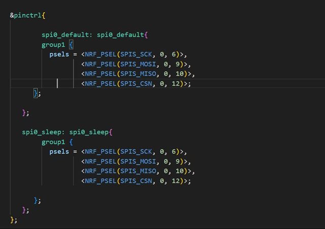
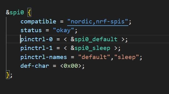
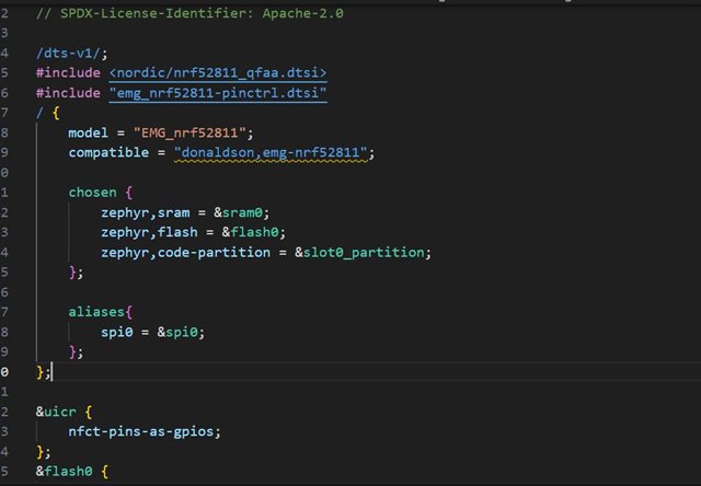
i have created pinctrl.dtsi and dts file as per below images. is this a correct way to configure SPI0 in salve mode?
I am using nrf connect SDK version 2.5.2
i have questions about:
1. CS pin whether i can use cs pin in pinctrl file or i have to use it as a gpio? if yes how to configure it (GPIO PIN or GPIOTE pin)
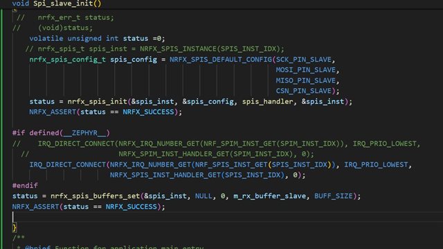
2. how to enable interrupt in spi slave mode to detect master has sent data
Any guidance, is greatly appreciated.