Issue with I2C communication in with multiple I2C sensors

Hello,

i'm going crazy trying to solve an issue involving I2C communication. I have the following setup: 

- ncs 2.4.2 (can't upload to latest because i have an issue with that...i have an issue open on DevZone)

- NRF5340DK

- I2C sensor A (TCS3400)

- I2C sensor B (MCP9808)

- I2C sensor C (LSM6DSOX)

- I2C sensor D (FDC1004)

I developed all the libraries to communicate with these sensors (yes, i know that many of them are supported by Zephyr but drivers were lacking many features such as interrupt, etc.). All the libraries have been tested arranging the breakouts of the sensors on a breadboard.

Now, this is the problem: when i try to read data from the FDC1004 (using the required sequence of commands: trigger measure -> check if measure is done -> read measure) AND the sensor A is connected, the "MEASURE_DONE" bit is NEVER set. Please note that the I2C function that reads the register is working (i can read the register content and all the other bits are correctly set). If i unplug the SDA or SCL or VDD for the breakout of sensor A the MEAS_DONE bit is instantly set.

Please note that:

- Connecting or disconnecting sensor B and C is totally irrelevant. If they are connected they work fine, if they are disconnected i still have the exact same problem with A and D. This exclude any problem about the loading of the SDA/SCL paths. Moreover, as i said, ALL the functions with ALL the sensors are working, with the exception of the function "isMeasDone()";

- The only function with this strange behaviour is "isMeasDone()". All the other functions set and read all the correct values in all the registers of every sensor;

- Each sensor by itself works with the code i wrote. This means that there are no issues with the addresses and the write/read functions;

- Sensors do not have the same I2C address. I double-checked it and, moreover, i highlight again that i have this issue ONLY with that specific function;

- The TCS3400 breakout is the only one without pull-up resistors for SDA and SCL on the board, but because of the fact that the other sensor breakouts have it, this is not needed. I measured the overall pull-up values (the parallel of all the pull-up of the several breakouts) is 5.2k, so this should be fine;

- Logging is active in the project. This allows me to track any error on the comunication...and there is not.

Unfortunately i cannot share the project because it has tens of source files and would be very unpractical. Here below you can find the definition of the of the function that is giving me trouble. Again, this function works perfectly if sensor A is not connected, so there should be no issue with the code....however...here you go:

bool fdc1004_isMeasDone(fdc1004_measCh_t measNum) { 

	//Read actual register value
	uint16_t regData = 0;
	if (fdc1004_read16(FDC1004_REG_FDC_CONF, &regData) != 0)
		return false;

	switch (measNum) {
		case FDC1004_MEAS1:
		return (regData & (1 << 3));
		break;
		case FDC1004_MEAS2:
		return (regData & (1 << 2));
		break;
		case FDC1004_MEAS3:
		return (regData & (1 << 1));
		break;
		case FDC1004_MEAS4:
		return (regData & (1 << 0));
		break;
	}	

	return false;
}

int fdc1004_read16(uint8_t regAddr, uint16_t* data) {
	
  // Initialize read and write buffers
  const uint8_t wbuffer = regAddr;
  uint8_t rbuffer[2];
	
  // Read register
  int ret = i2c_write_read_dt(fdc1004_dev,&wbuffer,1,rbuffer,2);
  if (ret != 0) {
	  LOG_ERR("%s error: Failed to read register 0x%0x", __func__, regAddr);
	  return SENSOR_ERROR_READ_FAILED;
    }

  // Prepare data to return
  *data = rbuffer[0]<<8|rbuffer[1];
  
  return SENSOR_SUCCESS;
}

Just for the sake of completeness, here below is the section of code that is generating my headache:

    // Perform measurement on channel 1
    fdc1004_triggerMeasure(FDC1004_MEAS1, true);
    while (!fdc1004_isMeasDone(FDC1004_MEAS1))      //ISSUE: THIS NEVER BECOMES TRUE WHEN SENSOR A IS CONNECTED!
    {
        k_busy_wait(100000);
    }
    fdc1004_getCapacitance(FDC1004_MEAS1, &capLevel);

I'm not able to get out of this on my own. I am not even able to understand if this is an hardware or a software issue. I hope your experience can provide me some hints to solve it.

Thank you,
Frax

Parents
  • This may be a simple bus loading issue; 5k2 is insufficient pull-up for 400kHz and only sufficient for a single device at 100kHz; for multiple devices 1k0 would be a better choice. The loading is more related to capacitive load than current load, since the capacitive load causes the slow rise times on I2C. Simple to test, make the pull-ups 1k0 and see if it starts working.

    A second issue may be the TCS3400 colour sensor; the threshold should match the application I2C voltage to minimise loading:

    TCS34001FNM 0x39 I²C VBUS = VDD Interface
    TCS34003FN  0x39 I²C bus = 1.8V Interface

    The last item to verify is that the I2C SCL and SDA ports are using H0D1 not S0D1. Indeed, SCL can use H0H1 if none of the I2C devices does clock-stretching or acts as a master.

  • Hi hmolesworth,

    thank you for your comments. Unfortunately what you suggested seems not to apply to my case. Let's go in order:

    1) I don't agree about the loading issue. In any case, i tried to check what i could and a) I2C speed is set to 100kHz and b) if i put 1k Ohm as pull-up. The result was that not a single sensor was able to communicate

    2) The TCS3400 that i'm using is the TCS34001FNM. As i said in the first post, i'm able to comunicate with all the sensors taken as single

    3) I still need to verify the H0D1/S0D1 element, but still i don't understand why because just 1 bit of tons of register comunication should be related with that :).

    I'm planning to use a logic analyzer soon. I'll keep the post updated. In the meantime, if anyone has any good idea is more than welcome

  • Here i am with new developments,

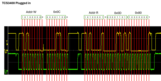
    At first, i understood why the I2C packets were messed up. This was my fault when, trying to fix my issue, i used a function "fdc1004_reset()" to reset the device just before setting up the acquisition parameters. Because i didn't wait for the device to fully reset, the device was not ready to set the acquisition parameters. After this fix, this is what i obtain from I2C analysis when i run the "isMeasDone()"  function:

    Everything is how it should be, with the exception of the "guilty" bit in the last byte, that should be 0x88 and not 0x80.

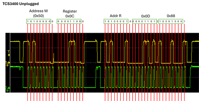
    When the TCS3400 is unplugged the situation changes:

    In this case everything is how it should be.

    Things i tried/discovered:

    - I tried to powerDown the TCS3400 during I2C transactions with FDC1004. Nothing changed.

    - I tried another FDC1004 chip. Nothing changes. Unfortunately, i have not another TCS3400 to test the same with the other sensor;

    - I studied the TCS3400 breakout and i discovered that there is an I2C EEPROM together with the TCS3400 sensor. Based on the breakout schematic that i found out on the AMS website, the EEPROM I2C address is 0xA0, so it should not create issues.

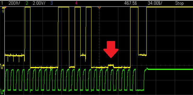
    - I noticed something that i want to remark, even if it could just be me being insanely suspicious. If you  zoom in the "TCS3400 plugged in" plot on the part where the "1" bit is missing, this is what you see

    In the very same spot where the bit should be "1", there is a very small bump (about 30-40 mV), exacty 1-clock cycle wide. I have no idea why it is like this and if it can be any relevant, but it's exactly where the "1" should be.

    Share your thoughts with me Slight smile

    Thank you

    Frax

  • Need spec on the e2 (EEPROM):

    "The seven bit address for the FDC1004 is (MSB first): b101 0000." which happens to be 0xA0 for a write, and 0xA1 for a read; highly suspicious .. "the EEPROM I2C address is 0xA0"

  • Hey, you 're right! Didn't notice at first! Now I'm out of office and quite burned out, but these are the EEPROM specs: BR24T04-W

    Link to the datasheet here below:

    https://www.rohm.com/datasheet?p=BR24T04FVM-W&dist=Mouser&media=referral&source=mouser.com&campaign=Mouser

    Tomorrow I'll read it carefully. I could try to unsolder it from the breakout, just in case!

    This is the best bet until now! Fingers crossed! 

    Frax

  • Yes, identical i2c address; change the e2 address by making one of the A0,A1,A2 pins Vdd instead of Gnd assuming the pins are exposed.

  • Unfortunately they are not exposed. That's why I didn't notice that the IC was an i2C EEPROM (I assumed that it was a voltage regulator or a level shifter, usual on this kind of board) and that's why I'm going to try to desolder it

Reply Children
Related