Multiple PPI channels with the same triggering timer event

Hi,

I'm trying to use 2 GPIOTE channels, 3 PPI channels, and a Timer instance in an application.

The 1st GPIOTE channel is input where it should trigger the Timer instance to start through PPI channel, at the same time I configured the "Timer compare event" to toggle the 2nd GPIOTE channel through PPI, and I configured the last PPI channel to stop the timer by its "compare event".

The channel configurations are as follows:

    status = nrfx_gppi_channel_alloc(&gppi_channel);
    NRFX_ASSERT(status == NRFX_SUCCESS);

    status = nrfx_gppi_channel_alloc(&gppi_channel_1);
    NRFX_ASSERT(status == NRFX_SUCCESS);

    status = nrfx_gppi_channel_alloc(&gppi_channel_2);
    NRFX_ASSERT(status == NRFX_SUCCESS);

    /*
     * Configure endpoints of the channel so that the input timer event is connected with the output
     * pin OUT task. This means that each time the timer interrupt occurs, the LED pin will be toggled.
     */
    nrfx_gppi_channel_endpoints_setup(gppi_channel,
        nrfx_timer_compare_event_address_get(&timer_inst, NRF_TIMER_CC_CHANNEL0),
        nrfx_gpiote_out_task_addr_get(OUTPUT_PIN));

    nrfx_gppi_channels_enable(BIT(gppi_channel));


    nrfx_gppi_channel_endpoints_setup(gppi_channel_1,
        nrfx_gpiote_in_event_addr_get(INPUT_PIN),
        nrfx_timer_task_address_get(&timer_inst, NRF_TIMER_TASK_START));

    nrfx_gppi_channels_enable(BIT(gppi_channel_1));


    nrfx_gppi_channel_endpoints_setup(gppi_channel_2,
        nrfx_timer_compare_event_address_get(&timer_inst, NRF_TIMER_CC_CHANNEL0),
        nrfx_timer_task_address_get(&timer_inst, NRF_TIMER_TASK_STOP));

    nrfx_gppi_channels_enable(BIT(gppi_channel_2));

But what happens is that the input pin trigger the timer to start and the timer stops itself but the output pin isn't changing.

The response from the DK:

[00:00:00.422,607] <inf> NRFX_EXAMPLE: Starting nrfx_gppi basic one-to-one example.
[00:00:00.430,694] <inf> NRFX_EXAMPLE: GPIOTE status: initialized
[00:00:00.430,725] <inf> NRFX_EXAMPLE: Time to wait: 1000 ms
[00:00:06.158,020] <inf> NRFX_EXAMPLE: GPIO input event callback
[00:00:07.158,325] <inf> NRFX_EXAMPLE: Timer finished. Context passed to the handler: >Some context<
[00:00:07.158,355] <inf> NRFX_EXAMPLE: GPIOTE output pin: 28 is high
[00:00:16.346,740] <inf> NRFX_EXAMPLE: GPIO input event callback
[00:00:16.586,303] <inf> NRFX_EXAMPLE: GPIO input event callback
[00:00:16.587,127] <inf> NRFX_EXAMPLE: GPIO input event callback
[00:00:17.347,320] <inf> NRFX_EXAMPLE: Timer finished. Context passed to the handler: >Some context<
[00:00:17.347,351] <inf> NRFX_EXAMPLE: GPIOTE output pin: 28 is high


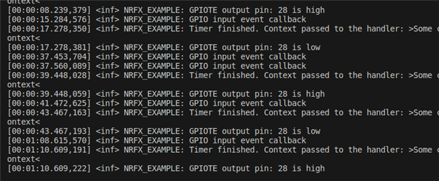
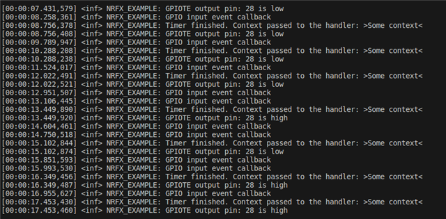
Even if I comment this line "nrfx_gppi_channels_enable(BIT(gppi_channel_2));" the behavior doesn't change, but when I comment the 3rd PPI channel configuration as follows and flash the code, the output pin starts to respond.

    status = nrfx_gppi_channel_alloc(&gppi_channel);
    NRFX_ASSERT(status == NRFX_SUCCESS);

    status = nrfx_gppi_channel_alloc(&gppi_channel_1);
    NRFX_ASSERT(status == NRFX_SUCCESS);

    status = nrfx_gppi_channel_alloc(&gppi_channel_2);
    NRFX_ASSERT(status == NRFX_SUCCESS);


    nrfx_gppi_channel_endpoints_setup(gppi_channel,
        nrfx_timer_compare_event_address_get(&timer_inst, NRF_TIMER_CC_CHANNEL0),
        nrfx_gpiote_out_task_addr_get(OUTPUT_PIN));

    nrfx_gppi_channels_enable(BIT(gppi_channel));


    nrfx_gppi_channel_endpoints_setup(gppi_channel_1,
        nrfx_gpiote_in_event_addr_get(INPUT_PIN),
        nrfx_timer_task_address_get(&timer_inst, NRF_TIMER_TASK_START));

    nrfx_gppi_channels_enable(BIT(gppi_channel_1));


    /*
    nrfx_gppi_channel_endpoints_setup(gppi_channel_2,
        nrfx_timer_compare_event_address_get(&timer_inst, NRF_TIMER_CC_CHANNEL0),
        nrfx_timer_task_address_get(&timer_inst, NRF_TIMER_TASK_STOP));
     */
//    nrfx_gppi_channels_enable(BIT(gppi_channel_2));


Also I noticed that the Input is triggered multiple times from the push button, is this related to the button bouncing?

[00:00:16.346,740] <inf> NRFX_EXAMPLE: GPIO input event callback
[00:00:16.586,303] <inf> NRFX_EXAMPLE: GPIO input event callback
[00:00:16.587,127] <inf> NRFX_EXAMPLE: GPIO input event callback

I'm using nrf5340DK, and NCS V2.4.0

My code is refactored from the "one_to_one" zephyr sample.

Best Regards,

Basem.

Parents
  • Hello Basem,

    Are you able to share the rest of your project? That might help me understand why it's failing.

    Also I noticed that the Input is triggered multiple times from the push button, is this related to the button bouncing?

    Most likely. There is no HW debouncing filter on the board. 

    Best regards,

    Vidar

  • Hello Vidar,

    Thanks for your response.

    As I said m code is refactored from the "one_to_one" zephyr sample, and here it is attached.

    #include <zephyr/logging/log_ctrl.h>
    #define NRFX_EXAMPLE_LOG_INIT()    LOG_INIT()
    #define NRFX_EXAMPLE_LOG_PROCESS() while (LOG_PROCESS())
    
    
    //#include <nrfx_example.h>
    #include <helpers/nrfx_gppi.h>
    #include <nrfx_timer.h>
    #include <nrfx_gpiote.h>
    
    #define NRFX_LOG_MODULE                 EXAMPLE
    #define NRFX_EXAMPLE_CONFIG_LOG_ENABLED 1
    #define NRFX_EXAMPLE_CONFIG_LOG_LEVEL   3
    #include <nrfx_log.h>
    
    /**
     * @defgroup nrfx_gppi_one_to_one_example One-to-one GPPI example
     * @{
     * @ingroup nrfx_gppi_examples
     *
     * @brief Example showing basic functionality of a nrfx_gppi helper.
     *
     * @details Application initializes nrfx_gpiote, nrfx_timer drivers and nrfx_gppi helper in a way that
     *          TIMER compare event is set up to be forwarded via PPI/DPPI to GPIOTE and toggle a pin.
     */
    
    /** @brief Symbol specifying timer instance to be used. */
    #define TIMER_INST_IDX 0
    
    /** @brief Symbol specifying time in milliseconds to wait for handler execution. */
    #define TIME_TO_WAIT_MS 2000UL
    
    /** @brief Symbol specifying ouput pin associated with the task. */
    #define OUTPUT_PIN DT_GPIO_PIN(DT_ALIAS(led0), gpios)
    
    #define INPUT_PIN DT_GPIO_PIN(DT_ALIAS(sw0), gpios)
    
    
    static void button_handler(nrfx_gpiote_pin_t pin,
    			   nrfx_gpiote_trigger_t trigger,
    			   void *context)
    {
    	LOG_INF("GPIO input event callback");
    }
    
    
    /**
     * @brief Function for handling TIMER driver events.
     *
     * @param[in] event_type Timer event.
     * @param[in] p_context  General purpose parameter set during initialization of the timer.
     *                       This parameter can be used to pass additional information to the handler
     *                       function for example the timer ID.
     */
    static void timer_handler(nrf_timer_event_t event_type, void * p_context)
    {
        if (event_type == NRF_TIMER_EVENT_COMPARE0)
        {
            char * p_msg = p_context;
            NRFX_LOG_INFO("Timer finished. Context passed to the handler: >%s<", p_msg);
            NRFX_LOG_INFO("GPIOTE output pin: %d is %s", OUTPUT_PIN,
                          nrfx_gpiote_in_is_set(OUTPUT_PIN) ? "high" : "low");
    		nrfx_gpiote_out_task_trigger(OUTPUT_PIN);
        }
    }
    
    /**
     * @brief Function for application main entry.
     *
     * @return Nothing.
     */
    int main(void)
    {
        nrfx_err_t status;
        (void)status;
    
        uint8_t in_channel, out_channel;
        uint8_t gppi_channel, gppi_channel_1, gppi_channel_2;
    
    #if defined(__ZEPHYR__)
        IRQ_DIRECT_CONNECT(NRFX_IRQ_NUMBER_GET(NRF_TIMER_INST_GET(TIMER_INST_IDX)), IRQ_PRIO_LOWEST,
                           NRFX_TIMER_INST_HANDLER_GET(TIMER_INST_IDX), 0);
        IRQ_DIRECT_CONNECT(NRFX_IRQ_NUMBER_GET(NRF_GPIOTE), IRQ_PRIO_LOWEST, nrfx_gpiote_irq_handler,
                           0);
    #endif
    
        NRFX_EXAMPLE_LOG_INIT();
    
        NRFX_LOG_INFO("Starting nrfx_gppi basic one-to-one example.");
        NRFX_EXAMPLE_LOG_PROCESS();


        status = nrfx_gpiote_init(NRFX_GPIOTE_DEFAULT_CONFIG_IRQ_PRIORITY);
        NRFX_ASSERT(status == NRFX_SUCCESS);
        NRFX_LOG_INFO("GPIOTE status: %s", nrfx_gpiote_is_init() ? "initialized" : "not initialized");
    
        status = nrfx_gpiote_channel_alloc(&out_channel);
        NRFX_ASSERT(status == NRFX_SUCCESS);
    
    	status = nrfx_gpiote_channel_alloc(&in_channel);
        NRFX_ASSERT(status == NRFX_SUCCESS);


        /*
         * Initialize output pin. The SET task will turn the LED on,
         * CLR will turn it off and OUT will toggle it.
         */
        static const nrfx_gpiote_output_config_t output_config =
        {
            .drive = NRF_GPIO_PIN_S0S1,
            .input_connect = NRF_GPIO_PIN_INPUT_DISCONNECT,
            .pull = NRF_GPIO_PIN_NOPULL,
        };
    
        const nrfx_gpiote_task_config_t task_config =
        {
            .task_ch = out_channel,
            .polarity = NRF_GPIOTE_POLARITY_TOGGLE,
            .init_val = NRF_GPIOTE_INITIAL_VALUE_HIGH,
        };
    
        status = nrfx_gpiote_output_configure(OUTPUT_PIN, &output_config, &task_config);
        NRFX_ASSERT(status == NRFX_SUCCESS);


    	/* Initialize input pin to generate event on high to low transition
    	 * (falling edge) and call button_handler()
    	 */
    	static const nrfx_gpiote_input_config_t input_config = {
    		.pull = NRF_GPIO_PIN_PULLUP,
    	};
    	const nrfx_gpiote_trigger_config_t trigger_config = {
    		.trigger = NRFX_GPIOTE_TRIGGER_HITOLO,
    		.p_in_channel = &in_channel,
    	};
    	static const nrfx_gpiote_handler_config_t handler_config = {
    		.handler = button_handler,
    	};
    	status = nrfx_gpiote_input_configure(INPUT_PIN, &input_config, &trigger_config, &handler_config);
        NRFX_ASSERT(status == NRFX_SUCCESS);


        nrfx_gpiote_out_task_enable(OUTPUT_PIN);
    	nrfx_gpiote_trigger_enable(INPUT_PIN, true);


        nrfx_timer_t timer_inst = NRFX_TIMER_INSTANCE(TIMER_INST_IDX);
        nrfx_timer_config_t timer_config = NRFX_TIMER_DEFAULT_CONFIG;
        timer_config.bit_width = NRF_TIMER_BIT_WIDTH_32;
        timer_config.p_context = "Some context";
    
        status = nrfx_timer_init(&timer_inst, &timer_config, timer_handler);
        NRFX_ASSERT(status == NRFX_SUCCESS);
    
        nrfx_timer_clear(&timer_inst);
    
        /* Creating variable desired_ticks to store the output of nrfx_timer_ms_to_ticks function. */
        uint32_t desired_ticks = nrfx_timer_ms_to_ticks(&timer_inst, TIME_TO_WAIT_MS);
        NRFX_LOG_INFO("Time to wait: %lu ms", TIME_TO_WAIT_MS);
    
        /*
         * Setting the timer channel NRF_TIMER_CC_CHANNEL0 in the extended compare mode to clear
         * the timer and to trigger an interrupt if the internal counter register is equal to
         * desired_ticks.
         */
        nrfx_timer_extended_compare(&timer_inst, NRF_TIMER_CC_CHANNEL0, desired_ticks,
                                    NRF_TIMER_SHORT_COMPARE0_CLEAR_MASK, true);


        status = nrfx_gppi_channel_alloc(&gppi_channel);
        NRFX_ASSERT(status == NRFX_SUCCESS);
    
        status = nrfx_gppi_channel_alloc(&gppi_channel_1);
        NRFX_ASSERT(status == NRFX_SUCCESS);
    
        status = nrfx_gppi_channel_alloc(&gppi_channel_2);
        NRFX_ASSERT(status == NRFX_SUCCESS);


        /*
         * Configure endpoints of the channel so that the input timer event is connected with the output
         * pin OUT task. This means that each time the timer interrupt occurs, the LED pin will be toggled.
         */
        nrfx_gppi_channel_endpoints_setup(gppi_channel,
            nrfx_timer_compare_event_address_get(&timer_inst, NRF_TIMER_CC_CHANNEL0),
            nrfx_gpiote_out_task_addr_get(OUTPUT_PIN));
    
        nrfx_gppi_channels_enable(BIT(gppi_channel));


        nrfx_gppi_channel_endpoints_setup(gppi_channel_1,
            nrfx_gpiote_in_event_addr_get(INPUT_PIN),
            nrfx_timer_task_address_get(&timer_inst, NRF_TIMER_TASK_START));
    
        nrfx_gppi_channels_enable(BIT(gppi_channel_1));


        nrfx_gppi_channel_endpoints_setup(gppi_channel_2,
            nrfx_timer_compare_event_address_get(&timer_inst, NRF_TIMER_CC_CHANNEL0),
            nrfx_timer_task_address_get(&timer_inst, NRF_TIMER_TASK_STOP));
    
        nrfx_gppi_channels_enable(BIT(gppi_channel_2));


        while (1)
        {
            NRFX_EXAMPLE_LOG_PROCESS();
        }
    }


    Best Regards,

    Basem

  • Hello Basem,

    This is more than refactoring. That said, I've copied and pasted your code into the one-to-one project but was unable to replicate the issue you encountered. Could you please try to program the zephyr.hex file included in the attached zip to see if you encounter the same problem?

    one_to_one_test.zip

    Best regards,

    Vidar

  • Thanks Vidar,

    But this isn't what I need to do, I'm sorry but I've sent you the wrong code and I didn't explain my issue well.

    I need the input pin to toggle the output pin and start the timer at the same time, and when the timer reach its compare value, toggle the output pin and stops itself, so that the output pin state is the same before starting the timer and after stopping it.

    The purpose behind this task is to control a dimmer circuit, where the circuit output is the zero-crossing signal (to my input pin) this zero-crossing signal needs to trigger the the DK output pin to be high for around (0.1 millisecond to 10 milliseconds) then it should back to the low state and repeat when zero-crossing detected.

    So, I thought that I can do that using GPIOTE, PPI, and Timers.

    Also I found the docs says:

    One event can trigger multiple tasks by subscribing different tasks to the same channel. Similarly, one task can be triggered by multiple events by publishing different events to the same channel. For advanced use cases, multiple events and multiple tasks can connect to the same channel forming a many-to-many connection. If multiple events are published on the same channel at the same time, the events are merged and only one event is routed through the DPPI.

    Then I edited the code to be as follows:

    #include <zephyr/logging/log_ctrl.h>
    #define NRFX_EXAMPLE_LOG_INIT()    LOG_INIT()
    #define NRFX_EXAMPLE_LOG_PROCESS() while (LOG_PROCESS())
    
    
    //#include <nrfx_example.h>
    #include <helpers/nrfx_gppi.h>
    #include <nrfx_timer.h>
    #include <nrfx_gpiote.h>
    
    #define NRFX_LOG_MODULE                 EXAMPLE
    #define NRFX_EXAMPLE_CONFIG_LOG_ENABLED 1
    #define NRFX_EXAMPLE_CONFIG_LOG_LEVEL   3
    #include <nrfx_log.h>
    
    /**
     * @defgroup nrfx_gppi_one_to_one_example One-to-one GPPI example
     * @{
     * @ingroup nrfx_gppi_examples
     *
     * @brief Example showing basic functionality of a nrfx_gppi helper.
     *
     * @details Application initializes nrfx_gpiote, nrfx_timer drivers and nrfx_gppi helper in a way that
     *          TIMER compare event is set up to be forwarded via PPI/DPPI to GPIOTE and toggle a pin.
     */
    
    /** @brief Symbol specifying timer instance to be used. */
    #define TIMER_INST_IDX 0
    
    /** @brief Symbol specifying time in milliseconds to wait for handler execution. */
    #define TIME_TO_WAIT_MS 500UL
    
    /** @brief Symbol specifying ouput pin associated with the task. */
    #define OUTPUT_PIN DT_GPIO_PIN(DT_ALIAS(led0), gpios)
    
    #define INPUT_PIN DT_GPIO_PIN(DT_ALIAS(sw0), gpios)
    
    
    static void button_handler(nrfx_gpiote_pin_t pin,
    			   nrfx_gpiote_trigger_t trigger,
    			   void *context)
    {
    	LOG_INF("GPIO input event callback");
    }
    
    
    /**
     * @brief Function for handling TIMER driver events.
     *
     * @param[in] event_type Timer event.
     * @param[in] p_context  General purpose parameter set during initialization of the timer.
     *                       This parameter can be used to pass additional information to the handler
     *                       function for example the timer ID.
     */
    static void timer_handler(nrf_timer_event_t event_type, void * p_context)
    {
        if (event_type == NRF_TIMER_EVENT_COMPARE0)
        {
            char * p_msg = p_context;
            NRFX_LOG_INFO("Timer finished. Context passed to the handler: >%s<", p_msg);
            NRFX_LOG_INFO("GPIOTE output pin: %d is %s", OUTPUT_PIN,
                          nrfx_gpiote_in_is_set(OUTPUT_PIN) ? "high" : "low");
    
    		// Toggle the output pin.
    		nrfx_gpiote_out_task_trigger(OUTPUT_PIN);
        }
    }
    
    /**
     * @brief Function for application main entry.
     *
     * @return Nothing.
     */
    int main(void)
    {
        nrfx_err_t status;
        (void)status;
    
        uint8_t in_channel, out_channel;
        uint8_t gppi_channel, gppi_channel_1, gppi_channel_2;
    
    #if defined(__ZEPHYR__)
        IRQ_DIRECT_CONNECT(NRFX_IRQ_NUMBER_GET(NRF_TIMER_INST_GET(TIMER_INST_IDX)), IRQ_PRIO_LOWEST,
                           NRFX_TIMER_INST_HANDLER_GET(TIMER_INST_IDX), 0);
        IRQ_DIRECT_CONNECT(NRFX_IRQ_NUMBER_GET(NRF_GPIOTE), IRQ_PRIO_LOWEST, nrfx_gpiote_irq_handler,
                           0);
    #endif
    
        NRFX_EXAMPLE_LOG_INIT();
    
        NRFX_LOG_INFO("Starting nrfx_gppi basic one-to-one example.");
        NRFX_EXAMPLE_LOG_PROCESS();


        status = nrfx_gpiote_init(NRFX_GPIOTE_DEFAULT_CONFIG_IRQ_PRIORITY);
        NRFX_ASSERT(status == NRFX_SUCCESS);
        NRFX_LOG_INFO("GPIOTE status: %s", nrfx_gpiote_is_init() ? "initialized" : "not initialized");
    
        status = nrfx_gpiote_channel_alloc(&out_channel);
        NRFX_ASSERT(status == NRFX_SUCCESS);
    
    	status = nrfx_gpiote_channel_alloc(&in_channel);
        NRFX_ASSERT(status == NRFX_SUCCESS);


        /*
         * Initialize output pin. The SET task will turn the LED on,
         * CLR will turn it off and OUT will toggle it.
         */
        static const nrfx_gpiote_output_config_t output_config =
        {
            .drive = NRF_GPIO_PIN_S0S1,
            .input_connect = NRF_GPIO_PIN_INPUT_DISCONNECT,
            .pull = NRF_GPIO_PIN_NOPULL,
        };
    
        const nrfx_gpiote_task_config_t task_config =
        {
            .task_ch = out_channel,
            .polarity = NRF_GPIOTE_POLARITY_TOGGLE,
            .init_val = NRF_GPIOTE_INITIAL_VALUE_HIGH,
        };
    
        status = nrfx_gpiote_output_configure(OUTPUT_PIN, &output_config, &task_config);
        NRFX_ASSERT(status == NRFX_SUCCESS);


    	/* Initialize input pin to generate event on high to low transition
    	 * (falling edge) and call button_handler()
    	 */
    	static const nrfx_gpiote_input_config_t input_config = {
    		.pull = NRF_GPIO_PIN_PULLUP,
    	};
    	const nrfx_gpiote_trigger_config_t trigger_config = {
    		.trigger = NRFX_GPIOTE_TRIGGER_HITOLO,
    		.p_in_channel = &in_channel,
    	};
    	static const nrfx_gpiote_handler_config_t handler_config = {
    		.handler = button_handler,
    	};
    	status = nrfx_gpiote_input_configure(INPUT_PIN, &input_config, &trigger_config, &handler_config);
        NRFX_ASSERT(status == NRFX_SUCCESS);


        nrfx_gpiote_out_task_enable(OUTPUT_PIN);
    	nrfx_gpiote_trigger_enable(INPUT_PIN, true);


        nrfx_timer_t timer_inst = NRFX_TIMER_INSTANCE(TIMER_INST_IDX);
        nrfx_timer_config_t timer_config = NRFX_TIMER_DEFAULT_CONFIG;
        timer_config.bit_width = NRF_TIMER_BIT_WIDTH_32;
        timer_config.p_context = "Some context";
    
        status = nrfx_timer_init(&timer_inst, &timer_config, timer_handler);
        NRFX_ASSERT(status == NRFX_SUCCESS);
    
        nrfx_timer_clear(&timer_inst);
    
        /* Creating variable desired_ticks to store the output of nrfx_timer_ms_to_ticks function. */
        uint32_t desired_ticks = nrfx_timer_ms_to_ticks(&timer_inst, TIME_TO_WAIT_MS);
        NRFX_LOG_INFO("Time to wait: %lu ms", TIME_TO_WAIT_MS);
    
        /*
         * Setting the timer channel NRF_TIMER_CC_CHANNEL0 in the extended compare mode to clear
         * the timer and to trigger an interrupt if the internal counter register is equal to
         * desired_ticks.
         */
        nrfx_timer_extended_compare(&timer_inst, NRF_TIMER_CC_CHANNEL0, desired_ticks,
                                    NRF_TIMER_SHORT_COMPARE0_CLEAR_MASK, true);


        status = nrfx_gppi_channel_alloc(&gppi_channel);
        NRFX_ASSERT(status == NRFX_SUCCESS);
    
        status = nrfx_gppi_channel_alloc(&gppi_channel_1);
        NRFX_ASSERT(status == NRFX_SUCCESS);
    
    
    	// The input pin is used to start the timer.
        nrfx_gppi_channel_endpoints_setup(gppi_channel,
            nrfx_gpiote_in_event_addr_get(INPUT_PIN),
            nrfx_timer_task_address_get(&timer_inst, NRF_TIMER_TASK_START));
    
    	// The input pin is used to toggle the output pin.
        nrfx_gppi_channel_endpoints_setup(gppi_channel,
            nrfx_gpiote_in_event_addr_get(INPUT_PIN),
            nrfx_gpiote_out_task_addr_get(OUTPUT_PIN));
    
        nrfx_gppi_channels_enable(BIT(gppi_channel));


    	// The timer stops itself on compare, and the timer ISR toggle the output pin.
        nrfx_gppi_channel_endpoints_setup(gppi_channel_1,
            nrfx_timer_compare_event_address_get(&timer_inst, NRF_TIMER_CC_CHANNEL0),
            nrfx_timer_task_address_get(&timer_inst, NRF_TIMER_TASK_STOP));
    
        nrfx_gppi_channels_enable(BIT(gppi_channel_1));


        while (1)
        {
            NRFX_EXAMPLE_LOG_PROCESS();
        }
    }
    
    /** @} */


    And it seems to be behave as I expected but when the timer is configured for (500 ms) and connecting the input pin with the on-board button 1 and the output pin with the on-board led 1.

    But when I configure the timer with e.g. (5 ms) and connect the input pin with the zero-crossing circuit, and the output pin with the circuit, and a common ground, the behavior changes, and it seems that the zero-crossing signal doesn't trigger the input pin to enable the timer nor affect the output pin (while I still using the pins connected to the on-board led 1 and button 1).

    Note:

    • I've tested the dimmer circuit using normal interrupts.

    Best regards,

    Basem

Reply
  • Thanks Vidar,

    But this isn't what I need to do, I'm sorry but I've sent you the wrong code and I didn't explain my issue well.

    I need the input pin to toggle the output pin and start the timer at the same time, and when the timer reach its compare value, toggle the output pin and stops itself, so that the output pin state is the same before starting the timer and after stopping it.

    The purpose behind this task is to control a dimmer circuit, where the circuit output is the zero-crossing signal (to my input pin) this zero-crossing signal needs to trigger the the DK output pin to be high for around (0.1 millisecond to 10 milliseconds) then it should back to the low state and repeat when zero-crossing detected.

    So, I thought that I can do that using GPIOTE, PPI, and Timers.

    Also I found the docs says:

    One event can trigger multiple tasks by subscribing different tasks to the same channel. Similarly, one task can be triggered by multiple events by publishing different events to the same channel. For advanced use cases, multiple events and multiple tasks can connect to the same channel forming a many-to-many connection. If multiple events are published on the same channel at the same time, the events are merged and only one event is routed through the DPPI.

    Then I edited the code to be as follows:

    #include <zephyr/logging/log_ctrl.h>
    #define NRFX_EXAMPLE_LOG_INIT()    LOG_INIT()
    #define NRFX_EXAMPLE_LOG_PROCESS() while (LOG_PROCESS())
    
    
    //#include <nrfx_example.h>
    #include <helpers/nrfx_gppi.h>
    #include <nrfx_timer.h>
    #include <nrfx_gpiote.h>
    
    #define NRFX_LOG_MODULE                 EXAMPLE
    #define NRFX_EXAMPLE_CONFIG_LOG_ENABLED 1
    #define NRFX_EXAMPLE_CONFIG_LOG_LEVEL   3
    #include <nrfx_log.h>
    
    /**
     * @defgroup nrfx_gppi_one_to_one_example One-to-one GPPI example
     * @{
     * @ingroup nrfx_gppi_examples
     *
     * @brief Example showing basic functionality of a nrfx_gppi helper.
     *
     * @details Application initializes nrfx_gpiote, nrfx_timer drivers and nrfx_gppi helper in a way that
     *          TIMER compare event is set up to be forwarded via PPI/DPPI to GPIOTE and toggle a pin.
     */
    
    /** @brief Symbol specifying timer instance to be used. */
    #define TIMER_INST_IDX 0
    
    /** @brief Symbol specifying time in milliseconds to wait for handler execution. */
    #define TIME_TO_WAIT_MS 500UL
    
    /** @brief Symbol specifying ouput pin associated with the task. */
    #define OUTPUT_PIN DT_GPIO_PIN(DT_ALIAS(led0), gpios)
    
    #define INPUT_PIN DT_GPIO_PIN(DT_ALIAS(sw0), gpios)
    
    
    static void button_handler(nrfx_gpiote_pin_t pin,
    			   nrfx_gpiote_trigger_t trigger,
    			   void *context)
    {
    	LOG_INF("GPIO input event callback");
    }
    
    
    /**
     * @brief Function for handling TIMER driver events.
     *
     * @param[in] event_type Timer event.
     * @param[in] p_context  General purpose parameter set during initialization of the timer.
     *                       This parameter can be used to pass additional information to the handler
     *                       function for example the timer ID.
     */
    static void timer_handler(nrf_timer_event_t event_type, void * p_context)
    {
        if (event_type == NRF_TIMER_EVENT_COMPARE0)
        {
            char * p_msg = p_context;
            NRFX_LOG_INFO("Timer finished. Context passed to the handler: >%s<", p_msg);
            NRFX_LOG_INFO("GPIOTE output pin: %d is %s", OUTPUT_PIN,
                          nrfx_gpiote_in_is_set(OUTPUT_PIN) ? "high" : "low");
    
    		// Toggle the output pin.
    		nrfx_gpiote_out_task_trigger(OUTPUT_PIN);
        }
    }
    
    /**
     * @brief Function for application main entry.
     *
     * @return Nothing.
     */
    int main(void)
    {
        nrfx_err_t status;
        (void)status;
    
        uint8_t in_channel, out_channel;
        uint8_t gppi_channel, gppi_channel_1, gppi_channel_2;
    
    #if defined(__ZEPHYR__)
        IRQ_DIRECT_CONNECT(NRFX_IRQ_NUMBER_GET(NRF_TIMER_INST_GET(TIMER_INST_IDX)), IRQ_PRIO_LOWEST,
                           NRFX_TIMER_INST_HANDLER_GET(TIMER_INST_IDX), 0);
        IRQ_DIRECT_CONNECT(NRFX_IRQ_NUMBER_GET(NRF_GPIOTE), IRQ_PRIO_LOWEST, nrfx_gpiote_irq_handler,
                           0);
    #endif
    
        NRFX_EXAMPLE_LOG_INIT();
    
        NRFX_LOG_INFO("Starting nrfx_gppi basic one-to-one example.");
        NRFX_EXAMPLE_LOG_PROCESS();


        status = nrfx_gpiote_init(NRFX_GPIOTE_DEFAULT_CONFIG_IRQ_PRIORITY);
        NRFX_ASSERT(status == NRFX_SUCCESS);
        NRFX_LOG_INFO("GPIOTE status: %s", nrfx_gpiote_is_init() ? "initialized" : "not initialized");
    
        status = nrfx_gpiote_channel_alloc(&out_channel);
        NRFX_ASSERT(status == NRFX_SUCCESS);
    
    	status = nrfx_gpiote_channel_alloc(&in_channel);
        NRFX_ASSERT(status == NRFX_SUCCESS);


        /*
         * Initialize output pin. The SET task will turn the LED on,
         * CLR will turn it off and OUT will toggle it.
         */
        static const nrfx_gpiote_output_config_t output_config =
        {
            .drive = NRF_GPIO_PIN_S0S1,
            .input_connect = NRF_GPIO_PIN_INPUT_DISCONNECT,
            .pull = NRF_GPIO_PIN_NOPULL,
        };
    
        const nrfx_gpiote_task_config_t task_config =
        {
            .task_ch = out_channel,
            .polarity = NRF_GPIOTE_POLARITY_TOGGLE,
            .init_val = NRF_GPIOTE_INITIAL_VALUE_HIGH,
        };
    
        status = nrfx_gpiote_output_configure(OUTPUT_PIN, &output_config, &task_config);
        NRFX_ASSERT(status == NRFX_SUCCESS);


    	/* Initialize input pin to generate event on high to low transition
    	 * (falling edge) and call button_handler()
    	 */
    	static const nrfx_gpiote_input_config_t input_config = {
    		.pull = NRF_GPIO_PIN_PULLUP,
    	};
    	const nrfx_gpiote_trigger_config_t trigger_config = {
    		.trigger = NRFX_GPIOTE_TRIGGER_HITOLO,
    		.p_in_channel = &in_channel,
    	};
    	static const nrfx_gpiote_handler_config_t handler_config = {
    		.handler = button_handler,
    	};
    	status = nrfx_gpiote_input_configure(INPUT_PIN, &input_config, &trigger_config, &handler_config);
        NRFX_ASSERT(status == NRFX_SUCCESS);


        nrfx_gpiote_out_task_enable(OUTPUT_PIN);
    	nrfx_gpiote_trigger_enable(INPUT_PIN, true);


        nrfx_timer_t timer_inst = NRFX_TIMER_INSTANCE(TIMER_INST_IDX);
        nrfx_timer_config_t timer_config = NRFX_TIMER_DEFAULT_CONFIG;
        timer_config.bit_width = NRF_TIMER_BIT_WIDTH_32;
        timer_config.p_context = "Some context";
    
        status = nrfx_timer_init(&timer_inst, &timer_config, timer_handler);
        NRFX_ASSERT(status == NRFX_SUCCESS);
    
        nrfx_timer_clear(&timer_inst);
    
        /* Creating variable desired_ticks to store the output of nrfx_timer_ms_to_ticks function. */
        uint32_t desired_ticks = nrfx_timer_ms_to_ticks(&timer_inst, TIME_TO_WAIT_MS);
        NRFX_LOG_INFO("Time to wait: %lu ms", TIME_TO_WAIT_MS);
    
        /*
         * Setting the timer channel NRF_TIMER_CC_CHANNEL0 in the extended compare mode to clear
         * the timer and to trigger an interrupt if the internal counter register is equal to
         * desired_ticks.
         */
        nrfx_timer_extended_compare(&timer_inst, NRF_TIMER_CC_CHANNEL0, desired_ticks,
                                    NRF_TIMER_SHORT_COMPARE0_CLEAR_MASK, true);


        status = nrfx_gppi_channel_alloc(&gppi_channel);
        NRFX_ASSERT(status == NRFX_SUCCESS);
    
        status = nrfx_gppi_channel_alloc(&gppi_channel_1);
        NRFX_ASSERT(status == NRFX_SUCCESS);
    
    
    	// The input pin is used to start the timer.
        nrfx_gppi_channel_endpoints_setup(gppi_channel,
            nrfx_gpiote_in_event_addr_get(INPUT_PIN),
            nrfx_timer_task_address_get(&timer_inst, NRF_TIMER_TASK_START));
    
    	// The input pin is used to toggle the output pin.
        nrfx_gppi_channel_endpoints_setup(gppi_channel,
            nrfx_gpiote_in_event_addr_get(INPUT_PIN),
            nrfx_gpiote_out_task_addr_get(OUTPUT_PIN));
    
        nrfx_gppi_channels_enable(BIT(gppi_channel));


    	// The timer stops itself on compare, and the timer ISR toggle the output pin.
        nrfx_gppi_channel_endpoints_setup(gppi_channel_1,
            nrfx_timer_compare_event_address_get(&timer_inst, NRF_TIMER_CC_CHANNEL0),
            nrfx_timer_task_address_get(&timer_inst, NRF_TIMER_TASK_STOP));
    
        nrfx_gppi_channels_enable(BIT(gppi_channel_1));


        while (1)
        {
            NRFX_EXAMPLE_LOG_PROCESS();
        }
    }
    
    /** @} */


    And it seems to be behave as I expected but when the timer is configured for (500 ms) and connecting the input pin with the on-board button 1 and the output pin with the on-board led 1.

    But when I configure the timer with e.g. (5 ms) and connect the input pin with the zero-crossing circuit, and the output pin with the circuit, and a common ground, the behavior changes, and it seems that the zero-crossing signal doesn't trigger the input pin to enable the timer nor affect the output pin (while I still using the pins connected to the on-board led 1 and button 1).

    Note:

    • I've tested the dimmer circuit using normal interrupts.

    Best regards,

    Basem

Children
  • Hello Basem,

    Basem Barakat said:
    But when I configure the timer with e.g. (5 ms) and connect the input pin with the zero-crossing circuit, and the output pin with the circuit, and a common ground, the behavior changes, and it seems that the zero-crossing signal doesn't trigger the input pin to enable the timer nor affect the output pin (while I still using the pins connected to the on-board led 1 and button 1).

    What about the IO voltage, does it match the output voltage from the zero-crossing circuit? Have you tried measuring this with a scope?

    Best regards,

    Vidar

  • Hello Vidar,

    and it seems that the zero-crossing signal doesn't trigger the input pin to enable the timer nor affect the output pin

    It seems that the GPIO pin isn't responding because it burnt out, so that the timer wasn't triggered.

    Is it possible for one GPIO pin to be burnt but the other GPIOs and the whole DK is still working?
    Is there a way to recover this GPIO pin?

    I've tried to simulate the zero-crossing signal by generating it using another DK using Timer, and tested my code and it seems to behave as I expect. The HW team will revise the dimmer circuit design and retest again after verifying that it free of problems.

    I'm not understand exactly what do you mean by that?

    This is more than refactoring

    Thank you very much Vidar for your support.

    Best regards,

    Basem

  • Yes, it's possible to damage only the input pin. This can happen if you exceed the Absolute maximum ratings on the pad. This is one of the reasons for why I wanted you to measure the signal output from your dimmer curcuit.

Related