SPIM: corrupted data by incoming SPIS data?

Hi,

we've run into an issue using the SPI master (SPIM). We got the NRF5340 connected to our FPGA using 2 spi busses. The NRF is SPI  master on one bus and SPI slave on the other. For testing, we're sending quite some transactions (1800/s receives on the slave, 400/s sends on master). Both busses only have MOSI, no MISO (so both are one-way). We use interrupts to notify the main code only, all SPIM transactions are started outside interrupts.

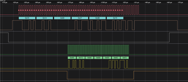
We always send/receive 7 bytes frames. Since we're testing, we also send known content (a header + cmd + sequence number + trailer). What we see if that sometimes (in order of 1:100.000) that the SPI master 'forgets' to send the last clock cycle of a transaction. So instead of sending 56 clock cycles (=7 bytes * 8)), it only sends 55. Other times it add 7 cycles.

The top 3 (Red/Brown/white) form the SPI_master's bus. The bottom 2 (missing CS there because we needed pin on logic analyser for other signal) show the incoming SPI transaction from the FPGA. The logic analyser marks all the rising flanks on the RED clock where it samples. The last byte only has 7 bits, so they are not marked.

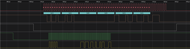
Zooming in on the top-left part:

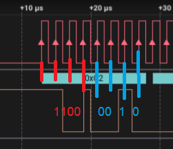
So the signal should only change on the falling edges of the clock and be samples (by the FPGA/logic analyser) on the rising edges. We expect the data to be C9 12 at start, but it's not. The small brown column at 19 usec is weird! It's only half a clock cycle long and the signal changes during the rising-edge of the clock?!?!

I suspect that's where the missing last clock cycle/bit gets 'eaten'. The 2nd byte is indeed shifted 1 bit (12 -> 24).

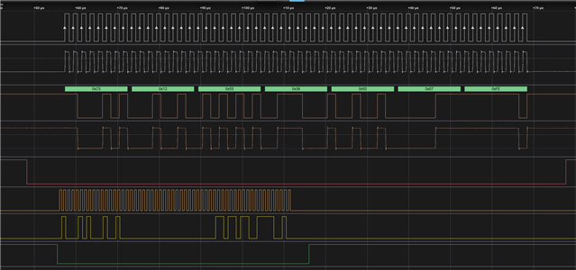
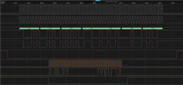
We have several different captures that show this behaviour.

We upgraded to NRFX 3.3 (latest), this seems to lower the frequence of this happening, but it still does. Disabling BLE did not change anything.

I suspect that sometimes, an incoming SPI slave transaction corrupts the data/state of the SPI master? But this is speculation.

Since the DevZone support was really helpful in solving our other issues, i hope you can repeat that again Slight smile

Parents
  • Hi,

    I have a few initial questions to understand more about the issue:

    • Do you see the missing clock cycle and corrupt data only on the logic analyzer, or also from the FPGA?
    • Which SPI mode have you configured on the nRF and the logic analyzer?
    • Which sampling rate are you using on the logic analyzer?

    The above is to try to establish if the issue is on the nRF side or if it could be something witht the test setup.

    If the problem is on the nRF side, I wonder if you are able to reproduce if you test with constant latency mode? If you run this from the app core, you can test that by making this call early in your application:

    NRF_POWER_NS->TASKS_CONSTLAT = 1; 

    I suspect that sometimes, an incoming SPI slave transaction corrupts the data/state of the SPI master? But this is speculation.

    It does no immediately seem likely, but do you have testing to back this up? Are you able to reproduce the issue if not usign SPIS?

  • Hello Einar,

    Thanks for the quick response.

    - The data issue was detected on the FPGA and then analyser on the logic analyser.

    - the mode is CPHA 0, CPOL 0

    - The analyser is sampling at 25 MS/s, so it has an accuracy of around 40 ns.

    I will run the test overnight with the modifications you mentioned. Currently it's happening roughly every 150.000 transfers.

    I'll update this post with the results..

  • I ran some tests with changes you advised:

    - I tried without BLE, still occured

    - I swapped SPIM3/SPIS2 with SPIM2/SPIS3, no effect, still occured.

    - I tried the memory regions mentioned, no change

    - I ran the test with CONSTLAT enabled. The test ran for around 500K transfers, then the issue occured again. I tried this once, because the test takes quite some time then, so a cautious conclusion would be then this does seems to help a bit.

    One more test I can still do, is to leave out the SPIS. That would mean changing the FPGA image and the setup since we test for timeouts by checking if a reply has been received over the SPIS. I could substitute this with a GPIO interrupt/poll to see if there was an error and just send on a timer.

  • Hi,

    Thank you for the update.

    As you have the test setup and if possible it would be interesting to know if there is a significant change in the frequency of this issue when enabling CONSTLAT or not, but I understand that can take some time.

    As you suspect a conflict with SPIS it would be very usefull with the results of the modified test you describe if possible.

    Is it possible to share the project you use to reproduce this?

  • Hello,

    I can test with only the SPIM, but this would require changing the FPGA image as well, since it needs to check the received SPI transfer and then report this back somehow (my idea is by a GPIO line we can poll).

    I will start on this test setup tomorrow.

    Our codebase runs on FreeRTOS and cannot be shared easily I'm afraid. I could send the SPI related code though..

  • Hi,

    I look forward to the results of your test.

    If you can share just your SPI related code and configurations that would be usefull (so that I have a better chance of reproducing the same issue on my end).

  • Hi,

    Have you had any progress on your end? Can you share the detailed configuration parameters you are using for SPI?

    I have a simple test application attached (spim-clock-cycle-missing-case-323334.zip) which I have used to attempt to reproduce the issue, but wiht no luck so far.

Reply Children
  • I'm still working on the test, I'm trying to port to to a version without OS, so it's easy to run for you. Here are at least the files that deal directly with the SPIM.

    We are sending around 600 transactions per second, each 7 bytes.

    spi_fragments.zip

    The code you attached is different of course, since it is based on Zephyr. The behaviour we have should be similar however. On a SPIM send irq, we schedule a main (=non-interrupt) timer to mark the SPI bus as not busy. On receive of a reply or a 10 ms timeout, we send the next transfer from the main code.

  • During the weekend I let the SPIM only test run. Out of the 10.000.000 transactions, NONE were faulty...

    In the end i also ran the BLE connection beside it (sending not much), that also didn't break the SPIM.

    I think the next test is having the FPGA send SPIS messages (not a reply but periodically)

  • I can reproduce the issue (usually within 5 minutes) with the FPGA sending 1000 spi transfers/sec to the Nordic, while the Nordic is sending around 1000 transfers/sec to the FPGA. They are unrelated in timing (different clocks). The Nordic transmit SPI clock is 500Khz, the FPGA SPI clock 1 Mhz.

    The top half is sending Nordic -> FPGA, the bottom half FPGA -> Nordic. The upper transfer should have been: (hex) C5 12 00 13 A5 8B (crc), but is C5 12 00 27 4B 15.

    This is a one-bit shift during byte 3: (that is 00, so cannot se exactly where)

    expect 13A58A    000100111010010110001010
    got      274B15   001001110100101100010101

    There are many many times the situation occurs where both transactions occur at the same time, so that's not it per se. What does cause this, I have no clue...

  • "The small brown column at 19 usec is weird! It's only half a clock cycle long and the signal changes during the rising-edge of the clock". Would it be possible to capture such an event on an oscilloscope instead of the logic analyser? The reason is the clock edge might not be as clean as the LA implies, and if a typical sloping rising/falling edge the clock spacing is not even. If the traces/wires between NRF and FPGA exceed (say) an inch there may be ringing at the clock threshold. Do both SCLK and MOSI from the nRF have H0H1 or E0E1 drive levels? Not, perish the thought, S0S1 .. Also does the FPGA SCLK line go near the nRF SCLK line?

  • We did the measurements here, also looking at the analog signals. They look ok. We also tried a different board, that also had the same issue. Here are 2 captures, one good and one bad (the good is right before the bad one in time).

    Good:

    Bad:

    The Top half is the outgoing SPI transfer, the bottom half the incoming transfer (to SPIS).

    We also changed the data we send, using 0x55330000 (bytes 3-6) as counter start to be able to better see if something changed.

    The first 2 bytes should be C5 12, followed by 55 38. What you can see is that one bit/clock between the 1 and 2 in byte 2 is just missing, turning 12 -> 14 and shifting the rest left one bit. An analog issue could not cause this in any way I think.

Related