Configuration of CTE data transmission and reception in low-power Bluetooth AOD mode using nrf5340dk

This is the video of my configuration process.

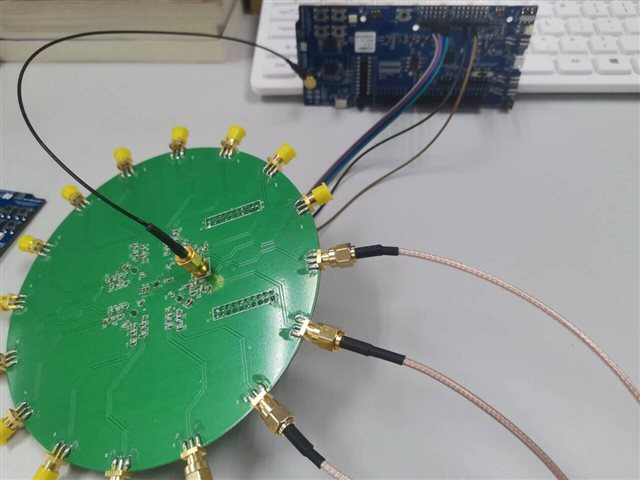
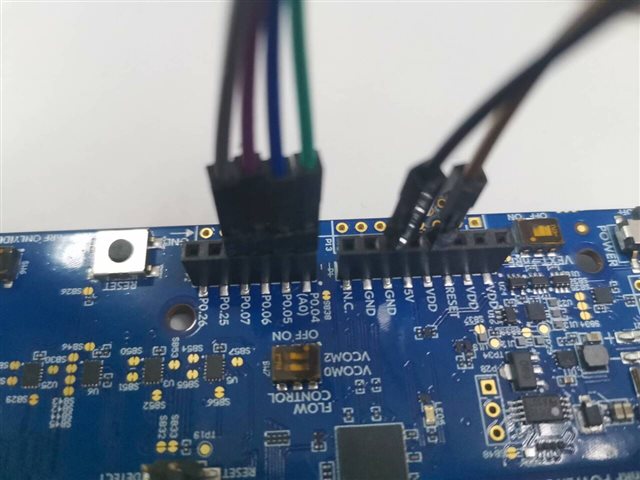
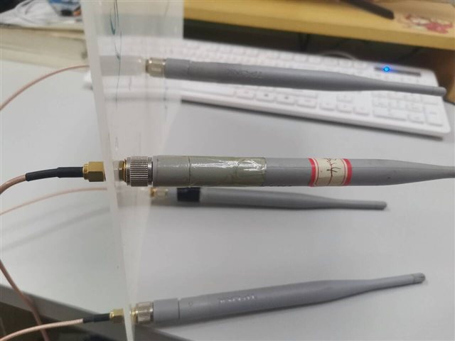
I want to use nfr5340-dk to achieve the transmission and reception of CTE data in low-power Bluetooth AOD mode. I imported the code for wireless transmission and reception in the SDK and configured it according to the example provided on the official website, but I did not successfully receive CTE data. It may be due to some errors in the configuration process. Could you please help me check which step went wrong? During this transmission and reception process, I used two NFR5340-DKs, which come with a built-in Bluetooth antenna. I do not have an external antenna matrix, so is it because my antenna switching mode is wrong? If I don't have an external antenna matrix, how should I configure it? The following are the steps and results of configuring according to the configuration tutorial provided on the official website:

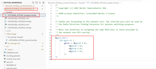
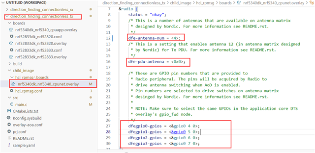
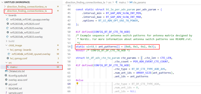
Bluetooth: Direction finding connectionless beacon

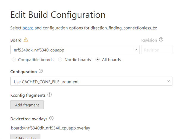
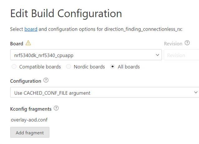
I didn't make any additional configurations, I just chose nrf5340dk as the development board

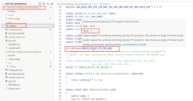
Bluetooth: Direction finding connectionless locator

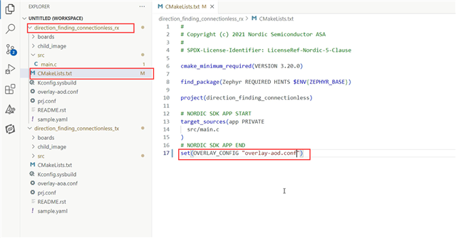
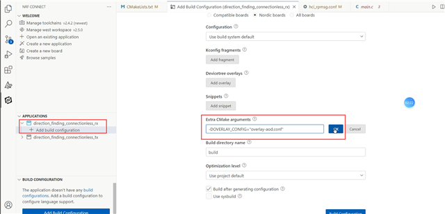
1.To build this sample with AoD mode only, set OVERLAY_CONFIG to the overlay-aod.conf file.

2.To build this sample for nRF5340 DK, with AoD mode only, add content of overlay-aod.conf file to child_image/hci_ipc.conf file.

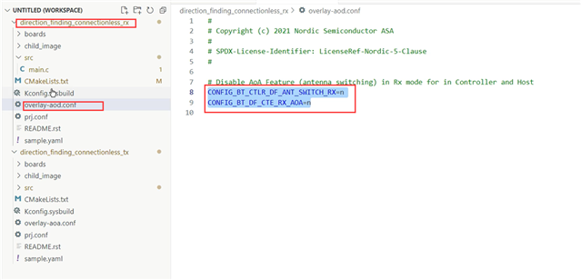
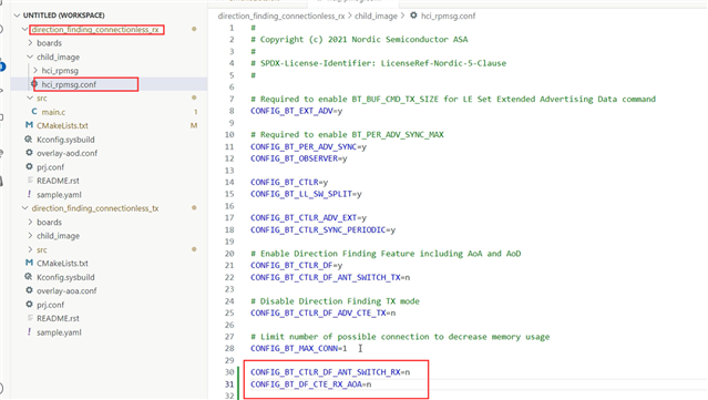
3.Result:Configured to only use AOD mode.

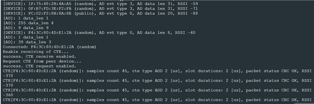
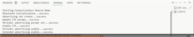
The result of programming the code onto the board

beacon:

locator:

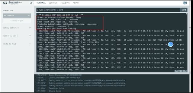
Obviously, it did not receive the CTE data sent by the sender.

  • Hello,

    One thing that typically is at fault when doing direction finding on the nRF5340 is that one forgets to configure the netcore with the right configurations as well as the appcore. That might remove some of the errors I saw in the video of yours, if that was something that persisted.

    Though what you show in that screenshot in the end is exactly what I would expect you to get with the "Direction finding connectionless" samples without an antenna matrix, both with nRF53, and nRF52833 etc. I guess the explanation there is that the uFL connector you would put in does not just add more to the antenna, but breaks the signal in a way. You could try inserting a uFL connector into the DK and see if that would be enough.

    If you want to try the samples with connection though (Direction finding central/peripheral) it will look a bit different, as I assume it manages to connect. But either way, I fail to see the point behind these tests, as you would need an external antenna matrix in order to test the direction finding functionality. What are you trying to test here?

    EDIT: Paal Kastnes in the chat is right, its an SWF connector. My mistake.

    Regards,

    Elfving

  • Thank you very much for your help!

    I tried the connection example and used the same configuration as before. As you said, it did connect successfully and received CTE data.

    I want to ensure that the basic wireless communication function works as expected through this test, and then add an antenna array to achieve the direction finding function.

    Do you mean that in the connectionless example, using my previous configuration, and connecting an antenna array to nrf5340dk through a UFL connector and configuring antenna switching mode can successfully achieve synchronization and receive CTE data?

  • One thing that typically is at fault when doing direction finding on the nRF5340 is that one forgets to configure the netcore with the right configurations as well as the appcore.

    This is already configured:

    Today, I added an antenna matrix using 4 antennas and configured ant_patterns based on the design of the antenna matrix.

    The antenna matrix is connected with four GPIOs on nrf5340dk to control antenna switching using DuPont Line.

    But the results are still the same as the last experiment.

  • So you connect an external antenna to the nRF5340-DK. What cable are you using? The connector in the DK is a SWF connector, it is NOT a UFL connector so you need an SWF cable to connect to the board. Not sure what happens if you use a UFL cable instead but it may mean you break the RF path.

  • This is not a problem with the cable. I connected the external antenna matrix with a cable and tested the connection example (Direction finding central/peripheral). When I only moved the board, the RSSI did not change much, while when I moved my external antenna, there was a significant change in RSSI, indicating that there was no problem with the cable.

    Four GPIOs used to control antenna switching are connected to the external antenna matrix via DuPont cables:

    This is the antenna:

Related