LIS2DH12 device is not ready issue

Hi,

I have added .overlay file as below mentioned 

&spi0 {
    status = "okay";   
    acc_lis2dh_spi: lis2dh@0 {
        compatible = "st,lis2dh";
        reg = <0>;
        spi-max-frequency = <10000000>;
        irq-gpios = <&gpio1 1 2>;
        label = "LIS2DH";
    };
};

And i have added my prj.config file as mentioned below.

CONFIG_STDOUT_CONSOLE=y
CONFIG_SPI=y
CONFIG_SENSOR=y
CONFIG_CBPRINTF_FP_SUPPORT=y
CONFIG_LIS2DH=y
CONFIG_LIS2DH_TRIGGER_GLOBAL_THREAD=y
CONFIG_PRINTK=y

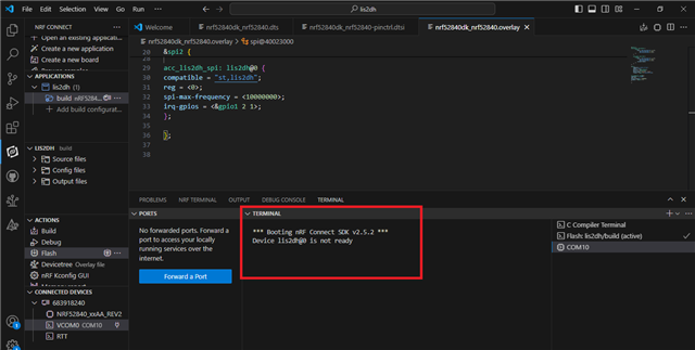
And I am facing issue is
Device LIS2DH is not ready with nrf52840dk.

So, can you please, help me with it.

Thanks & Regards,

Shaik Jareena.

Parents
  • Hi,

    Where do you specify the SPI pins such as SCLK, CS, MOSI, MISO?

    regards

    Jared 

  • Hi,

    I have added this pins like below mentioned and can you please, find this below.

    &spi1 {
        status = "okay";
        compatible = "nordic,nrf-spi";
        sck-pin = <0x23>;
        mosi-pin = <0x24>;
        miso-pin = <0x25>;
        cs-gpios = <&gpio1 1 GPIO_ACTIVE_LOW>;
        
        acc_lis2dh_spi: lis2dh@0 {
            compatible = "st,lis2dh";
            reg = <0>;
            spi-max-frequency = <10000000>;
            irq-gpios = <&gpio1 2 1>;
            label = "LIS2DH";
        };
    };
    And after this also, I am facing same issue device is not ready issue.
    Thanks & Regards,
    Shaik Jareena.
  • Hi,

    I provided the previous sample so that you can see how you should setup miso, sclk, and mosi using pinctrl. The CS pin is setup as a node by itself in the SPI node structure. I'm not sure what schematic you're asking for. The LIS2DH12 is not embedded on the nRF52840 DK. What pins have you physically connected the LIS2DH12 to the nRF52840 on?

    regards

    Jared 

  • Hi,

    I am connecting the pins as below mentioned in .overlay file, can you please, find this below.

    8306.nrf52840dk_nrf52840.overlay

    Can you please, find connections between LIS2DH12 sensor and nRF52840 module connections.

    LIS2DH12 JP2 header pins------------------------->nRF52840 pins

    JP1.1 PIN(VDD)------------------------------------------------->VDD

    JP2.22PIN(SDO)------------------------------------------------>P0.20

    JP2.21PIN(SDI)-------------------------------------------------->P0.21

    JP2.20PIN(SCL)------------------------------------------------->P0.19

    JP2.19PIN(CS)--------------------------------------------------->P1.12

    JP2.14PIN(INT1)------------------------------------------------->P1.02

    JP2.13PIN(GND)------------------------------------------------->GND

    After giving connections like this, I am getting this error as mentioned below marked in red color.

    So, can you please help me with this, Your help is more appreciable.

    Thanks & Regards,

    Shaik Jareena.

  • Hi,

    If you probe the SCLK, and then restart you program. Do you see any activity on the SCLK pin when the system initialize? Sometimes the driver tries to initialize the slave during init, if the slave doesn't respond then it might result in your error message,

    regards

    Jared 

  • Hi,

    I am getting this waveforms without connecting any pins and after connecting by pressing the reset button i am getting one clock like this below.

    i think it will not work by connecting my spi SCLK, MISO, MOSI and CS pins are p1.15,p1.14,p1.13 and p1.12 pins as per my schematic these are configured in spi3 in .dts file by using these pins and p1.02 as interrupt pin i have configures then also it is showing device is not ready only pin configurations I am suspecting because if hardware fault of sensor then it will show device is not found but device lis2dh12 gets found but not ready. So, in my .overlay file configuration only I am suspecting.

    I got one thing here any GPIO pin can be used for spi and interrupt pin and it is based on your board configuration only nrf52840dk.So, can you please, suggest which pins i need to configure for spi and Interrupt pin except QSPI pins.

    If any mistakes did you find in my .overlay file can you please, suggest.

    If possible can you please share i2c .overlay file by this I can know my sensor is working.

    Thanks & Regards,

    Shaik Jareena.

  • Hi,

    Jareena said:

    I am getting this waveforms without connecting any pins and after connecting by pressing the reset button i am getting one clock like this below.

    That doesn't look like a SCLK signal. 

    One easy way to see if the overlay has been applied correctly is to build your application and open the Devicetree GUI. You should then be able to see that the SPI node has been assigned to the specified pins. For example, when I build the SPIM nonblocking sample, and open the devicetree GUI, I see this:

    Can you try the same and confirm?

    regards

    Jared 

Reply
  • Hi,

    Jareena said:

    I am getting this waveforms without connecting any pins and after connecting by pressing the reset button i am getting one clock like this below.

    That doesn't look like a SCLK signal. 

    One easy way to see if the overlay has been applied correctly is to build your application and open the Devicetree GUI. You should then be able to see that the SPI node has been assigned to the specified pins. For example, when I build the SPIM nonblocking sample, and open the devicetree GUI, I see this:

    Can you try the same and confirm?

    regards

    Jared 

Children
No Data
Related