
Hi,
I'm trying to communicate with the DW1000, a radio transceiver and receiver that uses UWB technology. Unfortunately I couldn't find any examples on the Nordic or Zephyr sites.
After searching the internet, I found a library and examples within the Zephyr OS ecosystem that would allow communication with the DW1000 chip. The only problem is that the SPI implementation is missing. I also discovered a fully implemented SPI driver within the nRF SDK 15 that uses the same library. Using this, I created two projects: one with Zephyr OS, where I implemented the SPI driver, and another with the nRF SDK 15.
I'm working with a development kit that integrates both the nRF528232 and the DW1000 into a single chip. This integration is a pain because I can't use my logic analyzer to monitor the SPI pins for debugging purposes. So, I run a simple example where I am only reading out the chip ID from the DW1000. The project with nRF SDK 15 worked, meaning I got the correct ID back from the DW1000 (ID: 0xdeca0130). The project with Zephyr OS did not work, I got 0xFFFFFFFF. Most likely the bug is in SPI implementation. The simple example is waking up the DW1000 with a high pulse on the wake up pin, and resetting the DW1000 by pulling the reset pin to the ground for some time and then releasing it. Afterwards the ID is being read.
Below are both main, and the SPI implementation of the projects:
1. nRF Connect SDK project:
main.c:
#include <zephyr/kernel.h>
#include <zephyr/drivers/gpio.h>
#include <zephyr/drivers/spi.h>
#include <zephyr/logging/log.h>

#include "deca_device_api.h"
#include "deca_regs.h"
#include "deca_spi.h"
#include "port.h"


#include <hal/nrf_gpio.h>


#define DW1000_WAKE_UP NRF_GPIO_PIN_MAP(0,28)
#define DW1000_RST NRF_GPIO_PIN_MAP(0,25)

int main(void)
{
        int err = 0;
        uint32 r  = 0;

        // configure spi
        openspi();

        // wake up
        nrf_gpio_pin_clear(DW1000_WAKE_UP);
        nrf_gpio_cfg_output(DW1000_WAKE_UP);

        nrf_gpio_pin_set(DW1000_WAKE_UP);
        k_usleep(500);
        nrf_gpio_pin_clear(DW1000_WAKE_UP);
        k_msleep(2);

        // Reset dw1000
        nrf_gpio_pin_clear(DW1000_RST);
        nrf_gpio_cfg_output(DW1000_RST);
        k_msleep(2);
        nrf_gpio_cfg_input(DW1000_RST, NRF_GPIO_PIN_NOPULL);
        k_msleep(2);


        r = dwt_readdevid();
        if (DWT_DEVICE_ID == r)
        {
                printf("Correct UWB.");;
        }

        if (DWT_DEVICE_ID != r)
        {
                printf("Incorrect UWB.");;
                while(1){};
        }


        return 0;
}
SPI configuration[deca_dspi.c]:
 /*! ----------------------------------------------------------------------------
 * @file    deca_spi.c
 * @brief   SPI access functions
 *
 * @attention
 *
 * Copyright 2015 (c) DecaWave Ltd, Dublin, Ireland.
 * Copyright 2019 (c) Frederic Mes, RTLOC.
 *
 * All rights reserved.
 *
 * @author DecaWave
 */

#include "deca_device_api.h"
#include "deca_spi.h"
#include "port.h"

//zephyr includes
#include <errno.h>
#include <zephyr/kernel.h>
#include <zephyr/sys/printk.h>
#include <zephyr/device.h>
#include <zephyr/drivers/spi.h>
#include <hal/nrf_gpio.h>

//#include "nrf_drv_spi.h"

#define DW1000_CS_PIN NRF_GPIO_PIN_MAP(0,29) // pin 0.29 - CS PIN

#define SPI1_NODE		DT_NODELABEL(spi1)
#define BUFFER_LENGTH	128

static const struct device *spi;
struct spi_config *spi_cfg;
struct spi_config spi_cfgs[4]={0};

uint8_t tx_buf[BUFFER_LENGTH];
uint8_t rx_buf[BUFFER_LENGTH];

struct spi_buf bufs[2];

struct spi_buf_set tx;
struct spi_buf_set rx;

 *******************************************************************************/
/*! ------------------------------------------------------------------------------------------------------------------
 * Function: openspi()
 *
 * Low level abstract function to open and initialise access to the SPI device.
 * returns 0 for success, or -1 for error
 */
int openspi()
{
    spi_cfg = &spi_cfgs[0];

	spi = DEVICE_DT_GET(SPI1_NODE);
	if (!spi) {
		printk("Could not find SPI driver\n");
		return -1;
	}
	spi_cfg->operation =  SPI_TRANSFER_MSB | SPI_WORD_SET(8) | SPI_OP_MODE_MASTER /*| SPI_HOLD_ON_CS*/;
	spi_cfg->frequency = 2000000;


	nrf_gpio_cfg_output(DW1000_CS_PIN);
	nrf_gpio_pin_set(DW1000_CS_PIN);

	memset(&tx_buf[0], 0, BUFFER_LENGTH);
	memset(&rx_buf[0], 0, BUFFER_LENGTH);
	bufs[0].buf = &tx_buf[0];
	bufs[1].buf = &rx_buf[0];
	tx.buffers = &bufs[0];
	rx.buffers = &bufs[1];
	tx.count = 1;
	rx.count = 1;
    return 0;
} // end openspi()
SPI reading [deca_dspi.c]:
/*! ------------------------------------------------------------------------------------------------------------------
 * Function: readfromspi()
 *
 * Low level abstract function to read from the SPI
 * Takes two separate byte buffers for write header and read data
 * returns the offset into read buffer where first byte of read data may be found,
 * or returns 0
 */
//#pragma GCC push_options
//#pragma GCC optimize ("O0")
int readfromspi(uint16 headerLength,
                const uint8 *headerBuffer,
                uint32 readlength,
                uint8 *readBuffer)
{
    //decaIrqStatus_t  stat ;
    //stat = decamutexon() ;

	memset(&tx_buf[0], 0, headerLength+readlength);
	memcpy(&tx_buf[0], headerBuffer, headerLength);

    bufs[0].len = headerLength+readlength;
    bufs[1].len = headerLength+readlength;
	nrf_gpio_pin_clear(DW1000_CS_PIN);

    spi_transceive(spi, spi_cfg, &tx, &rx);
	/*
	do{
		spi_write(spi, spi_cfg, &tx);
		spi_read(spi, spi_cfg, &rx);
	}while(false);
	*/


	nrf_gpio_pin_set(DW1000_CS_PIN);

	memcpy(readBuffer, rx_buf+headerLength, readlength);

    //decamutexoff(stat);

    return 0;
} // end readfromspi()
//#pragma GCC pop_options
2. nRF SDK 15 project:
main.c:
 /******************************************************************************
 * @file    main.c
 * @author  Insight SiP
 * @version V1.0.0
 * @date    15-07-2019
 * @brief   simple uwb tx main file
 *
 * @attention
 *	THIS SOFTWARE IS PROVIDED BY INSIGHT SIP "AS IS" AND ANY EXPRESS
 *	OR IMPLIED WARRANTIES, INCLUDING, BUT NOT LIMITED TO, THE IMPLIED WARRANTIES
 *	OF MERCHANTABILITY, NONINFRINGEMENT, AND FITNESS FOR A PARTICULAR PURPOSE ARE
 *	DISCLAIMED. IN NO EVENT SHALL INSIGHT SIP OR CONTRIBUTORS BE
 *	LIABLE FOR ANY DIRECT, INDIRECT, INCIDENTAL, SPECIAL, EXEMPLARY, OR
 *	CONSEQUENTIAL DAMAGES (INCLUDING, BUT NOT LIMITED TO, PROCUREMENT OF SUBSTITUTE
 *	GOODS OR SERVICES; LOSS OF USE, DATA, OR PROFITS; OR BUSINESS INTERRUPTION)
 *	HOWEVER CAUSED AND ON ANY THEORY OF LIABILITY, WHETHER IN CONTRACT, STRICT
 *	LIABILITY, OR TORT (INCLUDING NEGLIGENCE OR OTHERWISE) ARISING IN ANY WAY OUT
 *	OF THE USE OF THIS SOFTWARE, EVEN IF ADVISED OF THE POSSIBILITY OF SUCH DAMAGE.
 *
 *****************************************************************************/

#include <stdbool.h>
#include <stdint.h>
#include <string.h>

#include "nordic_common.h"
#include "nrf.h"
#include "app_error.h"
#include "app_timer.h"
#include "nrf_drv_spi.h"
#include "nrf_drv_gpiote.h"
#include "nrf_gpio.h"
#include "nrf_pwr_mgmt.h"
#include "nrf_delay.h"

#include "boards.h"
#include "deca_device_api.h"
#include "deca_regs.h"

#include "nrf_log.h"
#include "nrf_log_ctrl.h"
#include "nrf_log_default_backends.h"


static nrf_drv_spi_t m_spi_instance = NRF_DRV_SPI_INSTANCE(0);
APP_TIMER_DEF(m_uwb_timer_id);

/**@brief Table specifying the default TX power parameters
*/
const uint32_t default_tx_power[14] =
{
    0x15355575,     // Channel 1 - 16M prf power
    0x07274767,     // Channel 1 - 64M prf power
    0x15355575,     // Channel 2 - 16M prf power
    0x07274767,     // Channel 2 - 64M prf power
    0x0f2f4f6f,     // Channel 3 - 16M prf power
    0x2b4b6b8b,     // Channel 3 - 64M prf power
    0x1f1f3f5f,     // Channel 4 - 16M prf power
    0x3a5a7a9a,     // Channel 4 - 64M prf power
    0x0E082848,     // Channel 5 - 16M prf power
    0x25456585,     // Channel 5 - 64M prf power
    0x0,            // Channel 6 - this is just a place holder
    0x0,            // Channel 6 - this is just a place holder
    0x32527292,     // Channel 7 - 16M prf power
    0x5171b1d1      // Channel 7 - 64M prf power
};


/**@brief Table specifying the default pg delay parameters
*/
const uint8_t default_pg_delay[7] =
{
    0xc9,     // Channel 1
    0xc2,     // Channel 2
    0xc5,     // Channel 3
    0x95,     // Channel 4
    0xc0,     // Channel 5
    0x0,      // Channel 6 - this is just a place holder
    0x93      // Channel 7
};


int readfromspi (uint16 headerLength, const uint8 *headerBuffer, uint32 readlength, uint8 *readBuffer)
{
    uint32 length = headerLength + readlength;

    uint8 m_spi_rx_buffer[length];
    uint8 m_spi_tx_buffer[length];
    memset(m_spi_rx_buffer, 0, length);
    memset(m_spi_tx_buffer, 0, length);

    memcpy(m_spi_tx_buffer, headerBuffer, headerLength);
    nrf_drv_spi_transfer(&m_spi_instance, m_spi_tx_buffer, length, m_spi_rx_buffer, length);
    memcpy(readBuffer, m_spi_rx_buffer+headerLength, readlength);

    return 0;
}


int writetospi(uint16 headerLength, const uint8 *headerBuffer, uint32 bodylength, const uint8 *bodyBuffer)
{
    uint32 length = headerLength + bodylength;

    uint8 m_spi_rx_buffer[length];
    uint8 m_spi_tx_buffer[length];
    memset(m_spi_rx_buffer, 0, length);
    memset(m_spi_tx_buffer, 0, length);

    memcpy(m_spi_tx_buffer, headerBuffer, headerLength);
    memcpy(m_spi_tx_buffer + headerLength, bodyBuffer, bodylength);
    nrf_drv_spi_transfer(&m_spi_instance, m_spi_tx_buffer, length, NULL, 0);

    return 0;
}


void decamutexoff(decaIrqStatus_t s)
{ }


decaIrqStatus_t decamutexon(void)
{
    return 0;
}


void deca_sleep(unsigned int time_ms)
{
    nrf_delay_ms(time_ms);
}


/**@brief DW1000 TX done event
 */
static void cb_tx_done (const dwt_cb_data_t *txd)
{
    NRF_LOG_INFO("UWB TX done.");
}


/**@brief DW1000 RX done event
 */
static void cb_rx_done (const dwt_cb_data_t *rxd)
{
    // Nothing to do
}


/**@brief DW1000 RX timeout event
 */
static void cb_rx_to (const dwt_cb_data_t *rxd)
{
    // Nothing to do
}


/**@brief DW1000 RX error event
 */
static void cb_rx_err (const dwt_cb_data_t *rxd)
{
    // Nothing to do
}


/**@brief GPIOTE event handler, executed in interrupt-context.
 */
static void gpiote_evt_handler(nrf_drv_gpiote_pin_t pin, nrf_gpiote_polarity_t action)
{
    uint32_t err_code;

    if ((pin == PIN_DW1000_IRQ) && (nrf_gpio_pin_read(PIN_DW1000_IRQ) == 1))
    {
        dwt_isr();
    }
}


/**@brief Initialize the GPIO tasks and events system to catch pin data ready interrupts.
 */
static uint32_t gpiote_init(void)
{
    uint32_t err_code;

    if (!nrf_drv_gpiote_is_init())
    {
        err_code = nrf_drv_gpiote_init();
        APP_ERROR_CHECK(err_code);
    }

    nrf_drv_gpiote_in_config_t gpiote_in_config;
    gpiote_in_config.is_watcher  = false;
    gpiote_in_config.hi_accuracy = false;
    gpiote_in_config.pull        = NRF_GPIO_PIN_NOPULL;
    gpiote_in_config.sense       = NRF_GPIOTE_POLARITY_LOTOHI;
    err_code = nrf_drv_gpiote_in_init(PIN_DW1000_IRQ, &gpiote_in_config, gpiote_evt_handler);
    APP_ERROR_CHECK(err_code);

    return NRF_SUCCESS;
}


/**@brief Initialize the SPI peripheral to communicate with dw1000.
 */
static uint32_t spi_init(void)
{
    uint32_t err_code;

    nrf_drv_spi_config_t spi_config = NRF_DRV_SPI_DEFAULT_CONFIG;
    spi_config.frequency = NRF_DRV_SPI_FREQ_2M;
    spi_config.miso_pin = PIN_DW1000_MISO;
    spi_config.mosi_pin = PIN_DW1000_MOSI;
    spi_config.sck_pin  = PIN_DW1000_CLK;
    spi_config.ss_pin   = PIN_DW1000_CS;

    err_code = nrf_drv_spi_init(&m_spi_instance, &spi_config, NULL, NULL);
    APP_ERROR_CHECK(err_code);

    return NRF_SUCCESS;
}


/**@brief Function for initializing the nrf log module.
 */
static void log_init(void)
{
    ret_code_t err_code = NRF_LOG_INIT(NULL);
    APP_ERROR_CHECK(err_code);

    NRF_LOG_DEFAULT_BACKENDS_INIT();
}


/**@brief Function for application main entry.
 */
int main(void)
{
    log_init();
    uint32 r  = 0;

    // Configure Wake up pin
    nrf_gpio_pin_clear(PIN_DW1000_WAKEUP);
    nrf_gpio_cfg_output(PIN_DW1000_WAKEUP);

    // Configure SPI
    spi_init();

    // Wake up
    nrf_gpio_pin_set(PIN_DW1000_WAKEUP);
    nrf_delay_us(500);   //500 us to wake up
    nrf_gpio_pin_clear(PIN_DW1000_WAKEUP);
    nrf_delay_ms(2);

    // Reset dw1000
    nrf_gpio_pin_clear(PIN_DW1000_RST);
    nrf_gpio_cfg_output(PIN_DW1000_RST);
    nrf_delay_ms(2);
    nrf_gpio_cfg_input(PIN_DW1000_RST, NRF_GPIO_PIN_NOPULL);
    nrf_delay_ms(2);


    r = dwt_readdevid();
    if (DWT_DEVICE_ID == r)
    {
        NRF_LOG_INFO("Correct UWB.");;
    }

    if (DWT_DEVICE_ID != r)
    {
        while(1){};
    }

    while(1){};

}
SPI configuration[main.c]:
/**@brief Initialize the SPI peripheral to communicate with dw1000.
 */
static uint32_t spi_init(void)
{
    uint32_t err_code;

    nrf_drv_spi_config_t spi_config = NRF_DRV_SPI_DEFAULT_CONFIG;
    spi_config.frequency = NRF_DRV_SPI_FREQ_2M;
    spi_config.miso_pin = PIN_DW1000_MISO;
    spi_config.mosi_pin = PIN_DW1000_MOSI;
    spi_config.sck_pin  = PIN_DW1000_CLK;
    spi_config.ss_pin   = PIN_DW1000_CS;

    err_code = nrf_drv_spi_init(&m_spi_instance, &spi_config, NULL, NULL);
    APP_ERROR_CHECK(err_code);

    return NRF_SUCCESS;
}
SPI reading [main.c]:
int readfromspi (uint16 headerLength, const uint8 *headerBuffer, uint32 readlength, uint8 *readBuffer)
{
    uint32 length = headerLength + readlength;

    uint8 m_spi_rx_buffer[length];
    uint8 m_spi_tx_buffer[length];
    memset(m_spi_rx_buffer, 0, length);
    memset(m_spi_tx_buffer, 0, length);

    memcpy(m_spi_tx_buffer, headerBuffer, headerLength);
    nrf_drv_spi_transfer(&m_spi_instance, m_spi_tx_buffer, length, m_spi_rx_buffer, length);
    memcpy(readBuffer, m_spi_rx_buffer+headerLength, readlength);

    return 0;
}
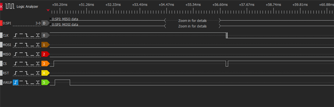
In order to see what is happening on the SPI pins, I used the board nrf52-DK and looked what the logic analyzer is giving me:
1. nRF Connect SDK project:
2. nRF SDK 15 project:
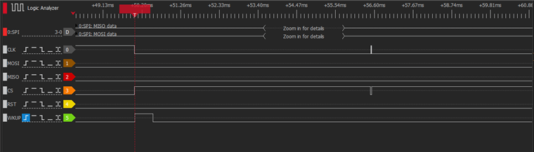
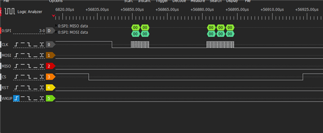
You can see the difference in the clock pin. In the nRF SDK 15 project the CLK is low when the SPI is configured. With the nRF Connect SDK the CLK pin is high until the data is sent. A small difference is that the nRF SDK sends all 5 bytes at once, with the nRF Connect SDK you can see that it sends 2 bytes first and then the rest. Below is a picture where I have zoomed in:
1. nRF Connect SDK project:
2. nRF SDK 15 project:
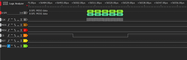
Could this difference be the reason why my SPI implementation does not work with the nRF Connect SDK? I've looked in the spi_config settings, searching for any flags that might keep the CS pin high until the transmission, but haven't found anything that could help me. Both of my projects are configured to use SPI mode 0 (with CPOL and CPHA set to zero).
Any advice or help would be greatly appreciated. If necessary, I can provide both projects for debugging.
Thanks for the help!

