Hi Supporter
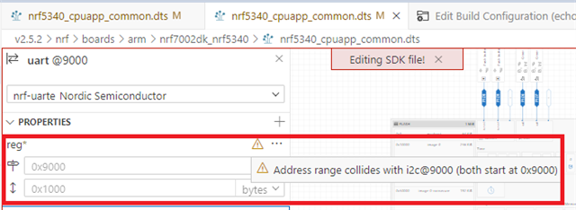
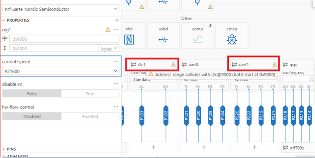
I use nRF7002-DK, toolchains and SDK version use v2.5.2, I try to modify Devicetree for nrf5340_app_common.dts file for add UART1 node, when I view visual editor as below, found UART1 and i2c register address was collidesed as below red color highlight, how can I escape or improve like that issue, Thanks.
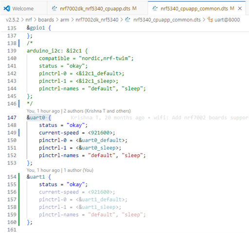
my nrf5340_cpuapp_common.dts as below
/*
* Copyright (c) 2022 Nordic Semiconductor ASA
*
* SPDX-License-Identifier: LicenseRef-Nordic-5-Clause
*/
#include "nrf5340_cpuapp_common-pinctrl.dtsi"
/ {
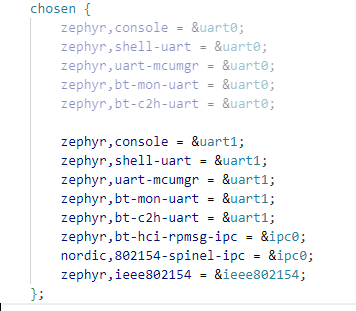
chosen {
zephyr,console = &uart0;
zephyr,shell-uart = &uart0;
zephyr,uart-mcumgr = &uart0;
zephyr,bt-mon-uart = &uart0;
zephyr,bt-c2h-uart = &uart0;
zephyr,bt-hci-rpmsg-ipc = &ipc0;
nordic,802154-spinel-ipc = &ipc0;
zephyr,ieee802154 = &ieee802154;
};
leds {
compatible = "gpio-leds";
led0: led_0 {
gpios = <&gpio1 6 GPIO_ACTIVE_HIGH>;
label = "Green LED 0";
};
led1: led_1 {
gpios = <&gpio1 7 GPIO_ACTIVE_HIGH>;
label = "Green LED 1";
};
};
pwmleds {
compatible = "pwm-leds";
pwm_led0: pwm_led_0 {
pwms = <&pwm0 0 PWM_MSEC(20) PWM_POLARITY_NORMAL>;
};
};
buttons {
compatible = "gpio-keys";
button0: button_0 {
gpios = <&gpio1 8 (GPIO_PULL_UP | GPIO_ACTIVE_LOW)>;
label = "Push button 1";
};
button1: button_1 {
gpios = <&gpio1 9 (GPIO_PULL_UP | GPIO_ACTIVE_LOW)>;
label = "Push button 2";
};
};
arduino_header: connector {
compatible = "arduino-header-r3";
#gpio-cells = <2>;
gpio-map-mask = <0xffffffff 0xffffffc0>;
gpio-map-pass-thru = <0 0x3f>;
gpio-map = <0 0 &gpio0 4 0>, /* A0 */
<1 0 &gpio0 5 0>, /* A1 */
<2 0 &gpio0 6 0>, /* A2 */
<3 0 &gpio0 7 0>, /* A3 */
<4 0 &gpio0 25 0>, /* A4 */
<5 0 &gpio0 26 0>, /* A5 */
<6 0 &gpio1 0 0>, /* D0 */
<7 0 &gpio1 1 0>, /* D1 */
<8 0 &gpio1 4 0>, /* D2 */
<9 0 &gpio1 5 0>, /* D3 */
<10 0 &gpio1 6 0>, /* D4 */
<11 0 &gpio1 7 0>, /* D5 */
<12 0 &gpio1 8 0>, /* D6 */
<13 0 &gpio1 9 0>, /* D7 */
<14 0 &gpio1 10 0>, /* D8 */
<15 0 &gpio1 11 0>, /* D9 */
<16 0 &gpio1 12 0>, /* D10 */
<17 0 &gpio1 13 0>, /* D11 */
<18 0 &gpio1 14 0>, /* D12 */
<19 0 &gpio1 15 0>, /* D13 */
<20 0 &gpio1 2 0>, /* D14 */
<21 0 &gpio1 3 0>; /* D15 */
};
arduino_adc: analog-connector {
compatible = "arduino,uno-adc";
#io-channel-cells = <1>;
io-channel-map = <0 &adc 0>, /* A0 = P0.4 = AIN0 */
<1 &adc 1>, /* A1 = P0.5 = AIN1 */
<2 &adc 2>, /* A2 = P0.6 = AIN2 */
<3 &adc 3>, /* A3 = P0.7 = AIN3 */
<4 &adc 4>, /* A4 = P0.25 = AIN4 */
<5 &adc 5>; /* A5 = P0.26 = AIN5 */
};
gpio_fwd: nrf-gpio-forwarder {
compatible = "nordic,nrf-gpio-forwarder";
status = "okay";
uart {
gpios = <&gpio1 1 0>, <&gpio1 0 0>, <&gpio1 5 0>, <&gpio1 4 0>;
};
};
nrf_radio_coex: nrf7002-coex {
status = "okay";
compatible = "nordic,nrf700x-coex";
req-gpios = <&gpio0 28 GPIO_ACTIVE_HIGH>;
status0-gpios = <&gpio0 30 GPIO_ACTIVE_HIGH>;
grant-gpios = <&gpio0 24 (GPIO_PULL_DOWN | GPIO_ACTIVE_LOW)>;
swctrl1-gpios = <&gpio0 29 GPIO_ACTIVE_HIGH>;
btrf-switch-gpios = <&gpio1 10 GPIO_ACTIVE_HIGH>;
};
/* These aliases are provided for compatibility with samples */
aliases {
led0 = &led0;
led1 = &led1;
pwm-led0 = &pwm_led0;
sw0 = &button0;
sw1 = &button1;
bootloader-led0 = &led0;
mcuboot-button0 = &button0;
mcuboot-led0 = &led0;
};
};
&adc {
status = "okay";
};
&gpiote {
status = "okay";
};
&gpio0 {
status = "okay";
};
&gpio1 {
status = "okay";
};
arduino_i2c: &i2c1 {
compatible = "nordic,nrf-twim";
status = "okay";
pinctrl-0 = <&i2c1_default>;
pinctrl-1 = <&i2c1_sleep>;
pinctrl-names = "default", "sleep";
};
&uart0 {
status = "okay";
current-speed = <921600>;
pinctrl-0 = <&uart0_default>;
pinctrl-1 = <&uart0_sleep>;
pinctrl-names = "default", "sleep";
};
&uart1 {
status = "okay";
current-speed = <921600>;
pinctrl-0 = <&uart1_default>;
pinctrl-1 = <&uart1_sleep>;
pinctrl-names = "default", "sleep";
};
&pwm0 {
status = "okay";
pinctrl-0 = <&pwm0_default>;
pinctrl-1 = <&pwm0_sleep>;
pinctrl-names = "default", "sleep";
};
&spi4 {
compatible = "nordic,nrf-spim";
status = "okay";
pinctrl-0 = <&spi4_default>;
pinctrl-1 = <&spi4_sleep>;
pinctrl-names = "default", "sleep";
cs-gpios = <&gpio0 11 GPIO_ACTIVE_LOW>;
mx25r64: mx25r6435f@0 {
compatible = "jedec,spi-nor";
reg = <0>;
spi-max-frequency = <33000000>;
jedec-id = [c2 28 17];
sfdp-bfp = [
e5 20 f1 ff ff ff ff 03 44 eb 08 6b 08 3b 04 bb
ee ff ff ff ff ff 00 ff ff ff 00 ff 0c 20 0f 52
10 d8 00 ff 23 72 f5 00 82 ed 04 cc 44 83 68 44
30 b0 30 b0 f7 c4 d5 5c 00 be 29 ff f0 d0 ff ff
];
size = <67108864>;
has-dpd;
t-enter-dpd = <10000>;
t-exit-dpd = <5000>;
};
};
&qspi {
status = "okay";
pinctrl-0 = <&qspi_default>;
pinctrl-1 = <&qspi_sleep>;
pinctrl-names = "default", "sleep";
nrf700x: nrf7002@1 {
status = "okay";
compatible = "nordic,nrf700x-qspi";
reg = <1>;
sck-frequency = <24000000>;
quad-mode;
/* Wi-Fi Pins used */
iovdd-ctrl-gpios = <&gpio0 31 GPIO_ACTIVE_HIGH>;
bucken-gpios = <&gpio0 12 GPIO_ACTIVE_HIGH>;
host-irq-gpios = <&gpio0 23 GPIO_ACTIVE_HIGH>;
};
};
arduino_serial: &uart1 {
compatible = "nordic,nrf-uarte";
current-speed = <921600>;
pinctrl-0 = <&uart1_default>;
pinctrl-1 = <&uart1_sleep>;
pinctrl-names = "default", "sleep";
};
arduino_spi: &spi3 {
compatible = "nordic,nrf-spim";
cs-gpios = <&arduino_header 16 GPIO_ACTIVE_LOW>; /* D10 */
pinctrl-0 = <&spi3_default>;
pinctrl-1 = <&spi3_sleep>;
pinctrl-names = "default", "sleep";
};
&flash0 {
partitions {
compatible = "fixed-partitions";
#address-cells = <1>;
#size-cells = <1>;
boot_partition: partition@0 {
label = "mcuboot";
reg = <0x00000000 0x00010000>;
};
slot0_partition: partition@10000 {
label = "image-0";
};
slot0_ns_partition: partition@50000 {
label = "image-0-nonsecure";
};
slot1_partition: partition@80000 {
label = "image-1";
};
slot1_ns_partition: partition@c0000 {
label = "image-1-nonsecure";
};
scratch_partition: partition@f0000 {
label = "image-scratch";
reg = <0x000f0000 0xa000>;
};
storage_partition: partition@fa000 {
label = "storage";
reg = <0x000fa000 0x00006000>;
};
};
};
&ieee802154 {
status = "okay";
};
zephyr_udc0: &usbd {
compatible = "nordic,nrf-usbd";
status = "okay";
};
/ {
reserved-memory {
#address-cells = <1>;
#size-cells = <1>;
ranges;
sram0_image: image@20000000 {
/* Zephyr image(s) memory */
};
sram0_s: image_s@20000000 {
/* Secure image memory */
};
sram0_ns: image_ns@20040000 {
/* Non-Secure image memory */
};
};
};
/* Include partition configuration file */
#include "nrf5340_cpuapp_partition_conf.dts"
Best Regards
Tina