Connecting the npm1300 to a custom board

Good Day.

I'm trying to run the "npm1300_fuel_gauge" example on a custom board (nRF52840), but I'm getting errors that I don't know how to fix. 

The first thing I did was to get the PMIC configuration overlay file (config.overlay) through nPM PowerUP. Then I transferred the code from config.overlay to the custom board device tree file (custom_board_nrf52840.dts). I plan to connect the PMIC via I2C1. 

custom_board_nrf52840.dts -->

&i2c1 {
	compatible = "nordic,nrf-twi";
	/* Cannot be used together with spi1. */
	status = "okay";
	pinctrl-0 = <&i2c1_default>;
	pinctrl-1 = <&i2c1_sleep>;
	pinctrl-names = "default", "sleep";

	npm1300_ek_pmic: pmic@6b {
		compatible = "nordic,npm1300";
		reg = <0x6b>;

		npm1300_ek_gpio: gpio-controller {
			compatible = "nordic,npm1300-gpio";
			gpio-controller;
			#gpio-cells = <2>;
			ngpios = <5>;
		};

		npm1300_ek_regulators: regulators {
			compatible = "nordic,npm1300-regulator";

	npm1300_ek_buck1: BUCK1 {
	 regulator-min-microvolt = <1000000>;
	 regulator-max-microvolt = <3300000>;
	 retention-microvolt = <1200000>;
	};

	npm1300_ek_buck2: BUCK2 {
	 regulator-min-microvolt = <1000000>;
	 regulator-max-microvolt = <3300000>;
	 retention-microvolt = <1800000>;
	};

	npm1300_ek_ldo1: LDO1 {
	 regulator-min-microvolt = <1000000>;
	 regulator-max-microvolt = <3300000>;

	 regulator-initial-mode = <NPM1300_LDSW_MODE_LDSW>;
	 // soft-start-microamp = <10000>;
	};

	npm1300_ek_ldo2: LDO2 {
	 regulator-min-microvolt = <1000000>;
	 regulator-max-microvolt = <3300000>;

	 regulator-initial-mode = <NPM1300_LDSW_MODE_LDSW>;
	 // soft-start-microamp = <10000>;
	};
	};

	npm1300_ek_charger: charger {
	 compatible = "nordic,npm1300-charger";
	 term-microvolt = <4200000>;
	 term-warm-microvolt = <3600000>;
	 // term-current-percent = <10>;
	 current-microamp = <100000>;
	 // trickle-microvolt = <2900000>;
	 dischg-limit-microamp = <1000000>;
	 vbus-limit-microamp = <500000>;
	 thermistor-ohms = <10000>;
	 thermistor-beta = <3380>;
	 charging-enable;
	};

	npm1300_ek_leds: leds {
	 compatible = "nordic,npm1300-led";
	 nordic,led0-mode = "error";
	  nordic,led1-mode = "charging";
	  nordic,led2-mode = "host";
	};
	};
};

custom_board_nrf52840-pinctrl.dtsi -->

i2c1_default: i2c1_default {
		group1 {
			psels = <NRF_PSEL(TWIM_SDA, 0, 15)>,
				<NRF_PSEL(TWIM_SCL, 0, 17)>;
			bias-pull-up;
		};
	};

	i2c1_sleep: i2c1_sleep {
		group1 {
			psels = <NRF_PSEL(TWIM_SDA, 0, 15)>,
				<NRF_PSEL(TWIM_SCL, 0, 17)>;
			low-power-enable;
		};
	};

The following errors occur in the .dts file (see screenshot).

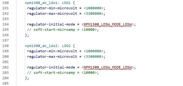
I know that these values should be taken from the "fuel_gauge.h" file, but that doesn't happen for some reason.

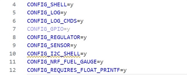
I see an error in the prj.conf file too (see screenshot). 

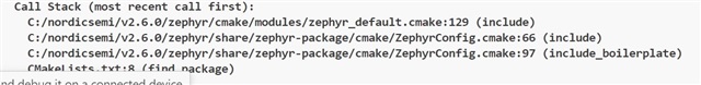
When building the project, I see the following information -->

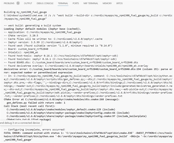
I have not changed the CMakeLists.txt files. 

# Copyright (c) 2023 Nordic Semiconductor ASA
# SPDX-License-Identifier: LicenseRef-Nordic-5-Clause

cmake_minimum_required(VERSION 3.20.0)

set(SHIELD npm1300_ek)

find_package(Zephyr REQUIRED HINTS $ENV{ZEPHYR_BASE})

project(my_npm1300_fuel_gauge)

add_subdirectory(src)

Can you please tell me where I am making a mistake when transferring this example to my custom board?

Thank you.

Parents
  • Hi,

    Looks like NPM1300_LDSW_MODE_LDSW is not defined for that file.

    So I searched for that in the nRF Connect SDK and found it used in zephyr/boards/shields/npm1300_ek/npm1300_ek.overlay.

    At the top of this file, there is an include:

    #include <dt-bindings/regulator/npm1300.h>
    

    Could you by chance, be missing this?

    Regards,
    Sigurd Hellesvik

  • Hi Sigurd, thank you for your response.

    Yes indeed, I didn't add that inclusion to the device tree file. After that, there was no error with the NPM1300_LDSW_MODE_LDSW detection.

    But cmake errors were still present.

    These errors were resolved by modifying the CMakeLists.txt file -->

    # Copyright (c) 2023 Nordic Semiconductor ASA
    # SPDX-License-Identifier: LicenseRef-Nordic-5-Clause
    
    cmake_minimum_required(VERSION 3.20.0)
    
    set(SHIELD npm1300_ek)
    
    find_package(Zephyr REQUIRED HINTS $ENV{ZEPHYR_BASE})
    project(NONE)
    
    # NORDIC SDK APP START
    target_sources(app PRIVATE
      src/main.c
      src/fuel_gauge.c
    )
    
    # NORDIC SDK APP END
    zephyr_library_include_directories(.)
    

    After that, the project build went through without errors. 

    But the application terminates (return 0) after -->

    if (!device_is_ready(charger)) {
    		LOG_DBG("Charger device not ready.\n");
    		return 0;
    	}

    Do you have any idea what this could be related to? All connections and jumpers are set according to the example.

    Also, I would like to ask if it is mandatory to use npm1300_ek.overlay? What is the point of using the config.overlay file from nPM PowerUP if it will be overwritten by npm1300_ek.overlay?

    Thanks.

  • One other thing I'm curious about...

    When profiling the battery, I set the voltage to 4.2V and the charge current to 120mA. If I now change these parameters (voltage and current) in the overlay file for PMIC, will it affect the algorithm for calculating the battery charge?

  • backstreet.devisor said:
    So I need to specify a lower value of V(TERM) than 4.2V (according to the technical documentation of the battery)? What is the usual value of V(TERM) set when charging such batteries? 

    I think V(TERM) is usually between 4.1V and 4.2V, but to be sure I have asked our PMIC experts.

    backstreet.devisor said:
    When profiling the battery, I set the voltage to 4.2V and the charge current to 120mA. If I now change these parameters (voltage and current) in the overlay file for PMIC, will it affect the algorithm for calculating the battery charge?

    I do not quite understand why you ask this?
    Myself, I do not know the algorithm, but it would make sense that changing the speed and max for a battery charge, you will affect the algorithm a bit. Like, it should show that you are done sooner if you choose 4.1V instead of 4.2V, no?

  • Hi.

    I got it. Thanks for your answers.

    This ticket can be considered closed. 

  • Sigurd Hellesvik said:
    I think V(TERM) is usually between 4.1V and 4.2V, but to be sure I have asked our PMIC experts.

    They say "The overlay file looks correct for his battery. "
    And they add some bonus info: "Once Vbat reaches 4.2V nPM1300 will keep charging in CV mode (Vbat 4.2V) until charge current drops to 0.1C (10% of Ichg), above the customer battery limit of 0.01C (1% of Ichg)."

    That is what you wanted to know, right?

  • Yes, that's what I wanted to know.

    But with this approach, I can never get to the point where charging stops as soon as the algorithm determines the charge level to be 100%.

    Let me give you an example.

    I have a device that shows the charge level on the display in % (according to the fuel_gauge algorithm), and a LED (CHG) whose state depends on the algorithm of the PMIC itself. 

    And I constantly have the situation that the display shows 100% charge level, but the CHG LED does not go to off state because I(TERM) is still too high for the PMIC to finish charging. And this behavior of the device can be misleading for the end user, as he will not know which indicator to trust (LED or display).

    I played around with the parameters in the overlay file (charge current and voltage), but I never managed to achieve a situation where the display shows 100% and the CHG LED turns off at the same time. Either 100% on the display and the LED is still on, or charging is turned off (LED turns off) but the algorithm shows less than 100% on the display.

    Anyway, thanks Sigurd for your patience and help, you can consider this ticket closed as the existing problem is beyond the scope of this ticket.

Reply
  • Yes, that's what I wanted to know.

    But with this approach, I can never get to the point where charging stops as soon as the algorithm determines the charge level to be 100%.

    Let me give you an example.

    I have a device that shows the charge level on the display in % (according to the fuel_gauge algorithm), and a LED (CHG) whose state depends on the algorithm of the PMIC itself. 

    And I constantly have the situation that the display shows 100% charge level, but the CHG LED does not go to off state because I(TERM) is still too high for the PMIC to finish charging. And this behavior of the device can be misleading for the end user, as he will not know which indicator to trust (LED or display).

    I played around with the parameters in the overlay file (charge current and voltage), but I never managed to achieve a situation where the display shows 100% and the CHG LED turns off at the same time. Either 100% on the display and the LED is still on, or charging is turned off (LED turns off) but the algorithm shows less than 100% on the display.

    Anyway, thanks Sigurd for your patience and help, you can consider this ticket closed as the existing problem is beyond the scope of this ticket.

Children
No Data
Related