I have a question about nPM1100 ERR, CHG pin.

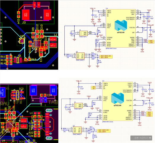
There was no problem when using the circuit below in the previous circuit,

After removing the USB part and changing the circuit as shown above, the input is that the CHG is disabled and charging is not possible as the ERR is activated. However, when I plugged in the charging cable and read the battery level, it seems to be charging.

Normal behavior is that ERR is disabled, and CHG should be activated/disabled when charging and discharging, but this is not the case.

Where should I look to find out the cause?

Parents
  • Hi,

    After removing the USB part and changing the circuit as shown above, the input is that the CHG is disabled and charging is not possible as the ERR is activated. However, when I plugged in the charging cable and read the battery level, it seems to be charging.

    The data signal pins for the USB peripheral needs to be in 1 of the possible configurations:

    In the second configuration if D+ and D- is connected to a USB host then ISET should be grounded. It seems that you have instead routed it out? Is because you want to control the charging current externally?

    After removing the USB part and changing the circuit as shown above, the input is that the CHG is disabled and charging is not possible as the ERR is activated. However, when I plugged in the charging cable and read the battery level, it seems to be charging.

    Normal behavior is that ERR is disabled, and CHG should be activated/disabled when charging and discharging, but this is not the case.

    So is it charging when you plug in the USB in the second configuration? 

    regards

    Jared 

Reply
  • Hi,

    After removing the USB part and changing the circuit as shown above, the input is that the CHG is disabled and charging is not possible as the ERR is activated. However, when I plugged in the charging cable and read the battery level, it seems to be charging.

    The data signal pins for the USB peripheral needs to be in 1 of the possible configurations:

    In the second configuration if D+ and D- is connected to a USB host then ISET should be grounded. It seems that you have instead routed it out? Is because you want to control the charging current externally?

    After removing the USB part and changing the circuit as shown above, the input is that the CHG is disabled and charging is not possible as the ERR is activated. However, when I plugged in the charging cable and read the battery level, it seems to be charging.

    Normal behavior is that ERR is disabled, and CHG should be activated/disabled when charging and discharging, but this is not the case.

    So is it charging when you plug in the USB in the second configuration? 

    regards

    Jared 

Children
Related