Attaching RTTviewer significantly changes interrupt characteristics

Hello,

nRF52840

ncs-v2.5.0-rc2

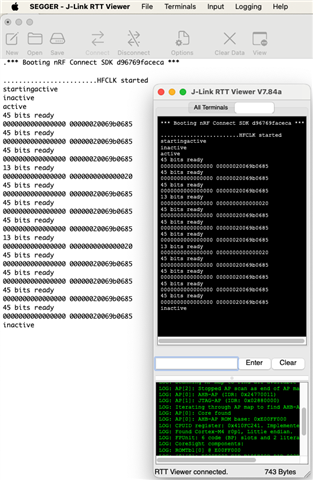
I am using a GPIO interrupt to trigger a callback on every edge on a particular GPIO. I am then timing the difference in time between interrupts in order to make calculations, such as decoding FSK and Manchester data. I got this to work really well but I was using the RTTviewer as my terminal. As soon as I disconnect the RTT terminal my algorithm stops working. I have discovered that the FSK data that I am getting is very well defined when the RTTviewer is attached. That is, there are very distinct frequencies. When I disconnect RTT the frequencies are much less defined and it becomes impossible to recover data from them.

Any reason why attaching RTTviewer would change the behavior of the interrupt? Timer? execution speed? thread handling (not that I even have extra threads..)?

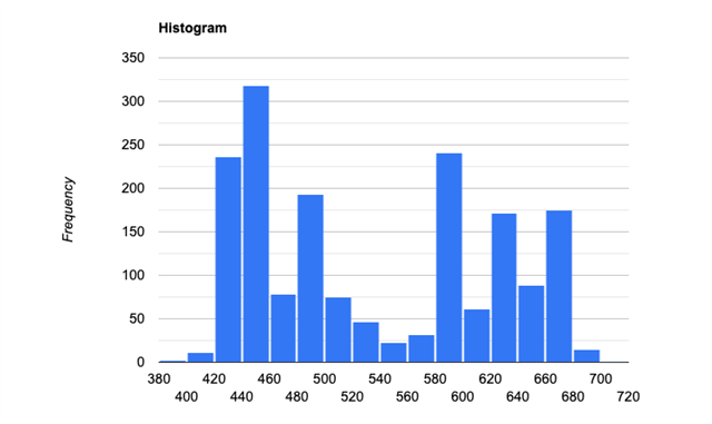
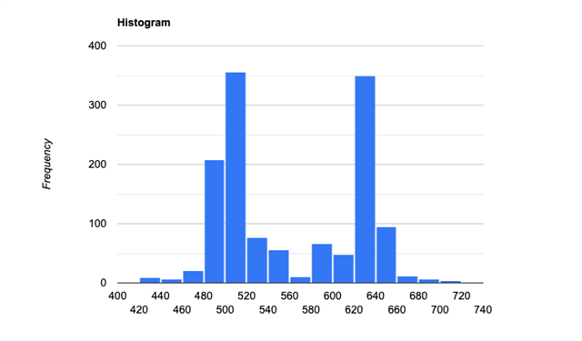
I have attached two histograms, showing time_diffs between interrupts with RTTviewer both attached and unattached.

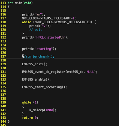
(psuedo code snippet)

void gpio_cb()
{
    this_time = get_time()
    time_diff = this_time - last_time // time_diff used later to make calculations and decide which frequency the FSK is operating at. WORKS WHEN RTTviewer IS ATTACHED!
    last_time = this_time
    ...
    //other calculations are made
    //works GREAT when RTTviewer is attached
    ...
}

Histogram of "time_diff" values without RTTviewer

Histogram of "time_diff" values with RTTviewer (literally just clicked connect->select correct options and MCU->okay, without even restarting it)

Thanks,

Nathan

Parents
  • Just to add some more explanation to the histograms above:

    I'm expecting two distinct frequencies (and therefore, periods) from my digital FSK signal. So by measuring the time_diff I'm able to measure the period between oscillations and decide which frequency it belongs to. If I take many time_diff (period) readings and plot them on a histogram, I should see two very distinct periods begin to emerge. The more clear these two periods are the better, as the algorithm would be able to place each time_diff reading in the correct category easier. I get a really good histogram when I attach the RTTviewer, as shown in the second histogram. However, in the first histogram the periods are more scattered about and less consistent. This leads to inconsistent behavior of the algorithm, especially down the line when it uses the demodulated FSK data to make more decisions.

    This could probably be handled in software by just fiddling with the quantization parameters. However, there are more problems still down the line when it comes to the timing of flipping between the two frequencies that I don't know would be fixed.

  • Debugging and RTT forces  HFCLK to be set.
    See SPIS: last byte missing if JTAG RTT disabled, otherwise ok

    Could this be the cause of your problem?

    Regards,
    Sigurd Hellesvik

  • Thanks, Sigurd.

    I gave your suggestion a try, and set the registers for turning on the HFCLK at the beginning of my program. The below recording shows how I placed the register settings at the top of my program, wait for the register to be set, then test it with/without RTTviewer connected. 

    I think this was a good idea.. maybe the HFCLK was getting unset even though I set it? I'll keep playing with it.

    Do you have any other ideas? This is a showstopper for us.

    Thanks!

  • Not sure if the video I posted went through. Here are some screenshots. 

    1. main() with HFCLK code added

    2. Terminal output without RTTviewer attached

    3. Terminal output with RTTviewer attached (same session, no MCU restart)

Reply Children
  • I did some more digging and I have some ideas here. The answer will likely be that you use PPI and a timer to measure this instead of the CPU.

    But first two questions:
    What is the lowest delay between two GPIO signals that you can get?
    Will you use BLE at the same time?

  • 1. The delay could be as low as 16kHz, but I've been designing for worst case 20kHz

    2. We are using BLE in prod, as well as NFC, UARTE, I2C, GPIO libraries. However, in the test program that I made the histograms with, I didn't use anything but the bare minimum, so nothing but GPIO.

    I considered using GPIOTE+PPI+TIMER but I have one question.. I need to have a callback function to process the delay data as it comes in. Would something like this work?

    GPIOTE->PPI------------>capture 16MHz timer

                       |----fork----->EGU-->callback function

  • Nathan45 said:
    We are using BLE in prod

    In this case, BLE interrupts will likely mess up your timings as well.
    Because of this, I would recommend using GPIOTE->PPI as you explain. I have been told that you do not need to use fork and EGU to handle the callback, so it should be a bit more straight forward.
    The possible catch is that with 16kHz sampling, you might get some issues handling all the callbacks fast enough.

    Does this make sense to you?

    We are a bit swamped after easter, so I'm not digging very far into this yet, and I hope that you are able to test some with PPI yourself. But let me know if you got any more questions!

  • Thanks for the help so far! I'll start looking into PPI.

    I do have a question I hope you can answer. I keep seeing conflicting information on the forums on how to use GPIOTE to trigger a peripheral task while also using the same GPIO to trigger a callback. I'm not sure how to do this? Can I use the normal Zephyr GPIO callback methods at the same time that I'm using GPIOTE stuff?

    Nathan

  • Nathan45 said:
    I do have a question I hope you can answer. I keep seeing conflicting information on the forums on how to use GPIOTE to trigger a peripheral task while also using the same GPIO to trigger a callback. I'm not sure how to do this? Can I use the normal Zephyr GPIO callback methods at the same time that I'm using GPIOTE stuff?

    I must admit that I have not tried this myself before, so I do not know.
    I asked one of my colleagues who is more experienced than me on this and thay say that they are not sure how easy this will be to combine. So its a "maybe works"

    However, if we take a step back and try to look at this from a bit more high level:

    Zephyr does not have drivers to support PPI, so you will have to use nrfx drivers for PPI and gpiote by directly calling nrfx_ functions.
    Zephyr as an operating system generally assumes that it has control over components, so in general cases I would say that you should be careful by mixing Zephyr and nrfx drivers for the same pins or peripherals.
    And since you already are using nrfx_ drivers for some things, maybe it is not that bad to use nrf_x drivers for GPIO callbacks on the relevant pins?

    Did I answer your question?

Related