nPM1300 one button example on custom board

Hi.

I'm testing the "nPM1300 One Button" example, but I'm having some problems. 

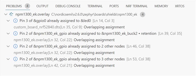
When setting up the npm1300_ek.overlay file, I specify that pin P0.15 is the interrupt pin on my custom board (nRF52840) and GPIO3 is the interrupt initiator pin on the PMIC, but I keep getting a warning that pin 3 is already in use in the device tree.

npm1300_ek.overlay -->

custom_board_nrf52840.dts -->

When I start an application, the LED connected to pin P0.03 on my board lights up (although it shouldn't). The interrupt does not work and the board does not respond to button presses on the nPM1300 EK.

Can you please advise me why this is happening and how to fix it?

Also by default there are problems in the overlay file related to pin 2 on the EK. Is there any way to fix them or will they not affect correct operation?
Thanks.

Parents
  • Hi 

    I presume your custom board is based on the 52840dk? 

    You can do the following in your overlay

    /{
        leds {
            status = "disabled";
        };
    }
    You can remove the 'leds' node altogether by using /delete-node/. The LED nodes are being referenced by the aliases, so those need to be removed as well.


    / {
        aliases {
            /delete-property/ led0;
            /delete-property/ mcuboot-led0;
            /delete-property/ bootloader-led0;
        };
    
        /delete-node/ leds;
    
    };

    Regards

    Runar

Reply
  • Hi 

    I presume your custom board is based on the 52840dk? 

    You can do the following in your overlay

    /{
        leds {
            status = "disabled";
        };
    }
    You can remove the 'leds' node altogether by using /delete-node/. The LED nodes are being referenced by the aliases, so those need to be removed as well.


    / {
        aliases {
            /delete-property/ led0;
            /delete-property/ mcuboot-led0;
            /delete-property/ bootloader-led0;
        };
    
        /delete-node/ leds;
    
    };

    Regards

    Runar

Children
  • Hi Runar. Thank you for your response.

    My board is based on the nRF52840 (it's not a DK). If I understand you correctly, if I disable the leds node, I can no longer use LEDs in my application? I don't want to do that because the LEDs on my board play an important role. 

    We need to find another solution to this problem.

    Why does the pmic-int-pin = <3> property configure the pin to nRF52840 and not nPM1300?

  • I agree, if that is the case I would not disable the leds. 

    Could you post your overlay so I can have a look at it? 

    Regards

    Runar

  • Here's these files:

    custom_board_nrf52840.dts -->

    #include <nordic/nrf52840_qiaa.dtsi>
    #include "custom_board_nrf52840-pinctrl.dtsi"
    
    / {
    	model = "custom board nRF52840";
    	compatible = "nordic-semiconductor,custom-board-nrf52840";
    
    	chosen {
    		zephyr,sram = &sram0;
    		zephyr,flash = &flash0;
    		zephyr,code-partition = &slot0_partition;
    		zephyr,console = &uart0;
    		zephyr,shell-uart = &uart0;
    		zephyr,uart-mcumgr = &uart0;
    	};
    
    	nrf_radio_fem: nrf21540_fem_node {
    		compatible  = "nordic,nrf21540-fem";
    		tx-en-gpios = <&gpio1 15 GPIO_ACTIVE_HIGH>;
    		rx-en-gpios = <&gpio0 2 GPIO_ACTIVE_HIGH>;
    		pdn-gpios   = <&gpio1 10 GPIO_ACTIVE_HIGH>;
    		spi-if = <&nrf_radio_fem_spi>;
    		supply-voltage-mv = <3300>;
        };
    
        leds {
            compatible = "gpio-leds";
    
    		led0: led_0 {
                gpios = <&gpio0 3 GPIO_ACTIVE_LOW>;
                label = "BT_LED_GREEN";
            };
    
    		led1: led_1 {
    			gpios = <&gpio0 11 GPIO_ACTIVE_LOW>;
                label = "LED_WHITE";
            };
    
    		led2: led_2 {
                gpios = <&gpio1 8 (GPIO_ACTIVE_LOW)>;
                label = "LED_RED";
            };
    
    		led3: led_3 {
                gpios = <&gpio0 27 (GPIO_ACTIVE_LOW)>;
                label = "LED_BLUE";
            };
    
    		led4: led_4 {
                gpios = <&gpio0 21 (GPIO_ACTIVE_LOW)>;
                label = "LED_GREEN";
            };
    
    		led5: led_5 {
                gpios = <&gpio0 22 (GPIO_ACTIVE_LOW)>;
                label = "LED_YELLOW";
            };
    
    		led6: led_6 {
                gpios = <&gpio0 23 (GPIO_ACTIVE_LOW)>;
                label = "LED_RED";
            };
    
    		speakeren: speaker_enable {
                gpios = <&gpio0 12 (GPIO_ACTIVE_HIGH)>;
                label = "SPEAKER_EN";
    		};
        };
    
    	pwmleds {
    		compatible = "pwm-leds";
    		pwmspeaker: pwm_speaker {
    			pwms = <&pwm0 0 PWM_HZ(800) PWM_POLARITY_NORMAL>;
    		};
    	};
    
    	buttons {
    		compatible = "gpio-keys";
    		button1: button_1 {
    			gpios = <&gpio0 30 (GPIO_PULL_UP | GPIO_ACTIVE_LOW)>;
    			label = "Button 1";
    		};
    	};
    
    	/* These aliases are provided for compatibility with samples */
    	aliases {
    		led0 = &led0;
    		led1 = &led1;
    		led2 = &led2;
    		led3 = &led3;
    		led4 = &led4;
    		led5 = &led5;
    		led6 = &led6;
    		speakeren = &speakeren;
    		pwmspeaker = &pwmspeaker;
    	};
    };
    
    &flash0 {
    	partitions {
    		compatible = "fixed-partitions";
    		#address-cells = <1>;
    		#size-cells = <1>;
    
    		boot_partition: partition@0 {
    			label = "mcuboot";
    			reg = <0x0 0xc000>;
    		};
    		slot0_partition: partition@c000 {
    			label = "image-0";
    			reg = <0xc000 0x72000>;
    		};
    		slot1_partition: partition@7e000 {
    			label = "image-1";
    			reg = <0x7e000 0x72000>;
    		};
    		scratch_partition: partition@f0000 {
    			label = "image-scratch";
    			reg = <0xf0000 0xa000>;
    		};
    		storage_partition: partition@fa000 {
    			label = "storage";
    			reg = <0xfa000 0x6000>;
    		};
    	};
    };
    
    
    &gpio0 {
        status = "okay";
    };
    
    &gpio1 {
        status = "okay";
    };
    
    &gpiote {
        status = "okay";
    };
    
    &uart0 {
    	status = "okay";
    	current-speed = <9600>;
    	pinctrl-0 = <&uart0_default>;
    	pinctrl-1 = <&uart0_sleep>;
    	pinctrl-names = "default", "sleep";
    };
    
    &i2c1 {
    	compatible = "nordic,nrf-twi";
    	/* Cannot be used together with spi1. */
    	status = "okay";
    	pinctrl-0 = <&i2c1_default>;
    	pinctrl-1 = <&i2c1_sleep>;
    	pinctrl-names = "default", "sleep";
    };
    
    &radio {
    	fem = <&nrf_radio_fem>;
    };
    
    &pwm0 {
    	status = "okay";
    	pinctrl-0 = <&pwm0_default>;
    	pinctrl-1 = <&pwm0_sleep>;
    	pinctrl-names = "default", "sleep";
    };

    npm1300_ek.overlay -->

    #include <dt-bindings/regulator/npm1300.h>
    #include <zephyr/dt-bindings/input/input-event-codes.h>
    
    &i2c1 {
    	npm1300_ek_pmic: pmic@6b {
    		compatible = "nordic,npm1300";
    		reg = <0x6b>;
    		host-int-gpios = <&gpio0 15 0>;
    		pmic-int-pin = <3>;
    
    		npm1300_ek_gpio: gpio-controller {
    			compatible = "nordic,npm1300-gpio";
    			gpio-controller;
    			#gpio-cells = <2>;
    			ngpios = <5>;
    		};
    
    		npm1300_ek_regulators: regulators {
    			compatible = "nordic,npm1300-regulator";
    
    			/* limits are set to min/max allowed values */
    			npm1300_ek_buck1: BUCK1 {
    				regulator-min-microvolt = <1800000>;
    				regulator-max-microvolt = <3300000>;
    			};
    
    			npm1300_ek_buck2: BUCK2 {
    				regulator-min-microvolt = <1000000>;
    				regulator-max-microvolt = <3300000>;
    				regulator-init-microvolt = <3300000>;
    				retention-microvolt = <2500000>;
    				enable-gpios = <&npm1300_ek_gpio 1 GPIO_ACTIVE_LOW>;
    				retention-gpios = <&npm1300_ek_gpio 2 GPIO_ACTIVE_HIGH>;
    				pwm-gpios = <&npm1300_ek_gpio 2 GPIO_ACTIVE_LOW>;
    			};
    
    			npm1300_ek_ldo1: LDO1 {
    				regulator-min-microvolt = <1000000>;
    				regulator-max-microvolt = <3300000>;
    				regulator-initial-mode = <NPM1300_LDSW_MODE_LDSW>;
    				enable-gpios = <&npm1300_ek_gpio 2 GPIO_ACTIVE_LOW>;
    			};
    
    			npm1300_ek_ldo2: LDO2 {
    				regulator-min-microvolt = <1000000>;
    				regulator-max-microvolt = <3300000>;
    				regulator-initial-mode = <NPM1300_LDSW_MODE_LDSW>;
    				enable-gpios = <&npm1300_ek_gpio 2 GPIO_ACTIVE_LOW>;
    			};
    		};
    
    		npm1300_ek_charger: charger {
    			compatible = "nordic,npm1300-charger";
    			term-microvolt = <4200000>;
    		  //term-warm-microvolt = <4200000>;
    			current-microamp = <120000>;
    			dischg-limit-microamp = <600000>;
    			vbus-limit-microamp = <500000>;
    			thermistor-ohms = <10000>;
    			thermistor-beta = <3380>;
    			charging-enable;
    		};
    
    		npm1300_ek_buttons: buttons {
    			compatible = "gpio-keys";
    			pmic_button0: pmic_button_0 {
    				gpios = < &npm1300_ek_gpio 0 GPIO_ACTIVE_HIGH>;
    				label = "Pmic button switch 0";
    			zephyr,code = <INPUT_KEY_0>;
    			};
    		};
    
    		npm1300_ek_leds: leds {
    			compatible = "nordic,npm1300-led";
    			nordic,led0-mode = "error";
    			nordic,led1-mode = "charging";
    			nordic,led2-mode = "host";
    		};
    	};
    };

  • Thanks

    When I look at the samples it looks like the npm1300 is defined in the overlay to the board. Not the npm1300. If you look at the zephyr dts in the build folder. Is the PMIC config included there? I will hopefully have an EK tomorrow and test myself

    Regards

    Runar

  • Hi. 

    Here is the part of the code associated with PMIC in the zephyr.dts file in the build folder. 

    zephyr.dts -->

    i2c1: i2c@40004000 {
    			compatible = "nordic,nrf-twi";
    			#address-cells = < 0x1 >;
    			#size-cells = < 0x0 >;
    			reg = < 0x40004000 0x1000 >;
    			clock-frequency = < 0x186a0 >;
    			interrupts = < 0x4 0x1 >;
    			easydma-maxcnt-bits = < 0x10 >;
    			status = "okay";
    			pinctrl-0 = < &i2c1_default >;
    			pinctrl-1 = < &i2c1_sleep >;
    			pinctrl-names = "default", "sleep";
    			npm1300_ek_pmic: pmic@6b {
    				compatible = "nordic,npm1300";
    				reg = < 0x6b >;
    				host-int-gpios = < &gpio0 0xf 0x0 >;
    				pmic-int-pin = < 0x3 >;
    				npm1300_ek_gpio: gpio-controller {
    					compatible = "nordic,npm1300-gpio";
    					gpio-controller;
    					#gpio-cells = < 0x2 >;
    					ngpios = < 0x5 >;
    					phandle = < 0xb >;
    				};
    				npm1300_ek_regulators: regulators {
    					compatible = "nordic,npm1300-regulator";
    					npm1300_ek_buck1: BUCK1 {
    						regulator-min-microvolt = < 0x1b7740 >;
    						regulator-max-microvolt = < 0x325aa0 >;
    					};
    					npm1300_ek_buck2: BUCK2 {
    						regulator-min-microvolt = < 0xf4240 >;
    						regulator-max-microvolt = < 0x325aa0 >;
    						regulator-init-microvolt = < 0x325aa0 >;
    						retention-microvolt = < 0x2625a0 >;
    						enable-gpios = < &npm1300_ek_gpio 0x1 0x1 >;
    						retention-gpios = < &npm1300_ek_gpio 0x2 0x0 >;
    						pwm-gpios = < &npm1300_ek_gpio 0x2 0x1 >;
    					};
    					npm1300_ek_ldo1: LDO1 {
    						regulator-min-microvolt = < 0xf4240 >;
    						regulator-max-microvolt = < 0x325aa0 >;
    						regulator-initial-mode = < 0x3 >;
    						enable-gpios = < &npm1300_ek_gpio 0x2 0x1 >;
    					};
    					npm1300_ek_ldo2: LDO2 {
    						regulator-min-microvolt = < 0xf4240 >;
    						regulator-max-microvolt = < 0x325aa0 >;
    						regulator-initial-mode = < 0x3 >;
    						enable-gpios = < &npm1300_ek_gpio 0x2 0x1 >;
    					};
    				};
    				npm1300_ek_charger: charger {
    					compatible = "nordic,npm1300-charger";
    					term-microvolt = < 0x401640 >;
    					current-microamp = < 0x1d4c0 >;
    					dischg-limit-microamp = < 0x927c0 >;
    					vbus-limit-microamp = < 0x7a120 >;
    					thermistor-ohms = < 0x2710 >;
    					thermistor-beta = < 0xd34 >;
    					charging-enable;
    				};
    				npm1300_ek_buttons: buttons {
    					compatible = "gpio-keys";
    					pmic_button0: pmic_button_0 {
    						gpios = < &npm1300_ek_gpio 0x0 0x0 >;
    						label = "Pmic button switch 0";
    						zephyr,code = < 0xb >;
    					};
    				};
    				npm1300_ek_leds: leds {
    					compatible = "nordic,npm1300-led";
    					nordic,led0-mode = "error";
    					nordic,led1-mode = "charging";
    					nordic,led2-mode = "host";
    				};
    			};
    		};

    Interruptions still don't work. Here is a screenshot from the logic analyzer (GPIO3 and SHPHLD button behavior). It might be of some help to you.

    Thanks.

Related