SPI can't read write sensor registers (USE Academy's sample code)

Hi supporter

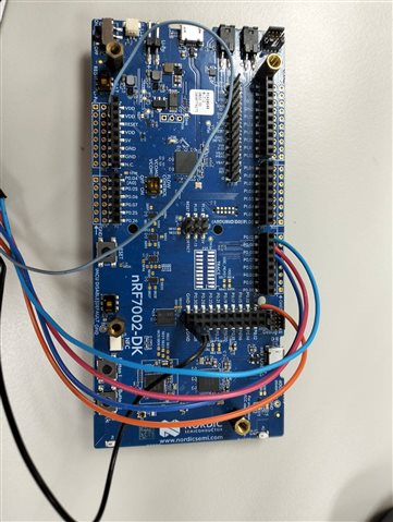
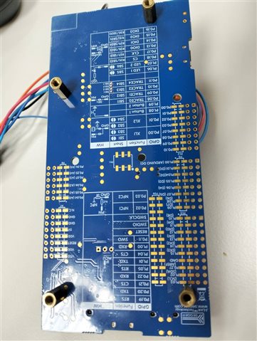
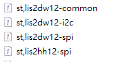
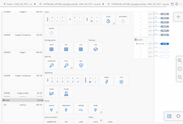
                  I use the sample "interfacing with a sensor over SPI"(academy.nordicsemi.com/.../), modified as BMP280 and ST-lis2hh12 sensor.I use vscode build environment, board:nRF7002_DK, SDK:v2.5.2.For SPI resource I use spi4 (CS:P0.11, SCK:P0.08, MOSI:P0.09, MISO:P0.10) , For this spi4 resource I short (SB11-SB14)on nRF7002_DK board to release the spi4 resource for my sensor.All setting and modify as academy's web side, all harware connection is solid, but the read and write registers on sensor result is "ZERO", when read and write registers no any error message.what did I miss for setting?Below is for read write result for BMP280 and ST-lis2hh12 value.please give suggestion for this issue, Thanks.   

FOR BMP280 read write result

00:00:00.253,509] <inf> Lesson5_Exercise1: -------------------------------------------------------------
[00:00:00.253,509] <inf> Lesson5_Exercise1: bmp_read_calibrationdata: Reading from calibration registers:
[00:00:00.253,601] <inf> Lesson5_Exercise1: Reg[0x88] 2 Bytes read: Param T1 = 0
[00:00:00.303,771] <inf> Lesson5_Exercise1: Reg[0x8a] 2 Bytes read: Param T2 = 0
[00:00:00.353,912] <inf> Lesson5_Exercise1: Reg[0x8c] 2 Bytes read: Param T3 = 0
[00:00:00.404,083] <inf> Lesson5_Exercise1: Reg[0x8e] 2 Bytes read: Param P1 = 0
[00:00:00.454,254] <inf> Lesson5_Exercise1: Reg[0x90] 2 Bytes read: Param P2 = 0
[00:00:00.504,425] <inf> Lesson5_Exercise1: Reg[0x92] 2 Bytes read: Param P3 = 0
[00:00:00.554,626] <inf> Lesson5_Exercise1: Reg[0x94] 2 Bytes read: Param P4 = 0
[00:00:00.604,766] <inf> Lesson5_Exercise1: Reg[0x96] 2 Bytes read: Param P5 = 0
[00:00:00.654,937] <inf> Lesson5_Exercise1: Reg[0x98] 2 Bytes read: Param P6 = 0
[00:00:00.705,108] <inf> Lesson5_Exercise1: Reg[0x9a] 2 Bytes read: Param P7 = 0
[00:00:00.755,279] <inf> Lesson5_Exercise1: Reg[0x9c] 2 Bytes read: Param P8 = 0
[00:00:00.805,480] <inf> Lesson5_Exercise1: Reg[0x9e] 2 Bytes read: Param P9 = 0
[00:00:00.855,590] <inf> Lesson5_Exercise1: bmp_print_registers: Reading all BMP280 registers (one by one)
[00:00:00.855,651] <inf> Lesson5_Exercise1: Reg[0xd0] = 0x00
[00:00:00.875,823] <inf> Lesson5_Exercise1: Reg[0xa1] = 0x00
[00:00:00.895,965] <inf> Lesson5_Exercise1: Reg[0xa2] = 0x00
[00:00:00.916,107] <inf> Lesson5_Exercise1: Reg[0xa3] = 0x00
[00:00:00.936,248] <inf> Lesson5_Exercise1: Reg[0xa4] = 0x00
[00:00:00.956,390] <inf> Lesson5_Exercise1: Reg[0xa5] = 0x00
[00:00:00.976,531] <inf> Lesson5_Exercise1: Reg[0xa6] = 0x00
[00:00:00.996,673] <inf> Lesson5_Exercise1: Reg[0xa7] = 0x00
[00:00:01.016,845] <inf> Lesson5_Exercise1: Reg[0xa8] = 0x00
[00:00:01.036,987] <inf> Lesson5_Exercise1: Reg[0xa9] = 0x00
[00:00:01.057,128] <inf> Lesson5_Exercise1: Reg[0xaa] = 0x00
[00:00:01.077,270] <inf> Lesson5_Exercise1: Reg[0xab] = 0x00
[00:00:01.097,412] <inf> Lesson5_Exercise1: Reg[0xac] = 0x00
[00:00:01.117,553] <inf> Lesson5_Exercise1: Reg[0xad] = 0x00
[00:00:01.137,695] <inf> Lesson5_Exercise1: Reg[0xae] = 0x00
[00:00:01.157,836] <inf> Lesson5_Exercise1: Reg[0xaf] = 0x00
[00:00:01.177,978] <inf> Lesson5_Exercise1: Reg[0xb0] = 0x00
[00:00:01.198,120] <inf> Lesson5_Exercise1: Reg[0xf4] = 0x00
[00:00:01.218,292] <inf> Lesson5_Exercise1: Reg[0xf5] = 0x00
[00:00:01.238,433] <inf> Lesson5_Exercise1: Reg[0xf6] = 0x00
[00:00:01.258,575] <inf> Lesson5_Exercise1: Reg[0xf7] = 0x00
[00:00:01.278,717] <inf> Lesson5_Exercise1: Reg[0xf8] = 0x00
[00:00:01.298,858] <inf> Lesson5_Exercise1: Reg[0xf9] = 0x00
[00:00:01.319,000] <inf> Lesson5_Exercise1: Reg[0xfa] = 0x00
[00:00:01.339,141] <inf> Lesson5_Exercise1: Reg[0xfb] = 0x00
[00:00:01.359,283] <inf> Lesson5_Exercise1: Reg[0xfc] = 0x00
[00:00:01.379,425] <inf> Lesson5_Exercise1: Reg[0xfd] = 0x00
[00:00:01.399,566] <inf> Lesson5_Exercise1: Reg[0xfe] = 0x00
[00:00:01.419,738] <inf> Lesson5_Exercise1: Reg[0xff] = 0x00
[00:00:01.439,819] <inf> Lesson5_Exercise1: -------------------------------------------------------------
[00:00:01.439,849] <inf> Lesson5_Exercise1: Continuously read sensor samples, compensate, and display
[00:00:01.439,910] <inf> Lesson5_Exercise1: Temperature: uncomp = 0 C comp = 0.00 C
[00:00:01.439,941] <inf> Lesson5_Exercise1: Pressure: uncomp = 0 Pa comp = 0.00 Pa
[00:00:02.440,093] <inf> Lesson5_Exercise1: Temperature: uncomp = 0 C comp = 0.00 C
[00:00:02.440,093] <inf> Lesson5_Exercise1: Pressure: uncomp = 0 Pa comp = 0.00 Pa
[00:00:03.440,307] <inf> Lesson5_Exercise1: Temperature: uncomp = 0 C comp = 0.00 C
[00:00:03.440,307] <inf> Lesson5_Exercise1: Pressure: uncomp = 0 Pa comp = 0.00 Pa
[00:00:04.440,490] <inf> Lesson5_Exercise1: Temperature: uncomp = 0 C comp = 0.00 C
[00:00:04.440,490] <inf> Lesson5_Exercise1: Pressure: uncomp = 0 Pa comp = 0.00 Pa
[00:00:05.440,704] <inf> Lesson5_Exercise1: Temperature: uncomp = 0 C comp = 0.00 C
[00:00:05.440,704] <inf> Lesson5_Exercise1: Pressure: uncomp = 0 Pa comp = 0.00 Pa

FOR ST-lis2hh12 read write result

*** Booting nRF Connect SDK v2.5.2 ***
[00:00:00.250,366] <inf> Lesson5_Exercise1: -------------------------------------------------------------
[00:00:00.250,366] <inf> Lesson5_Exercise1: lis_read_calibrationdata: Reading from calibration registers:
[00:00:00.250,396] <inf> Lesson5_Exercise1: Reg[0x0b] 2 Bytes read: Param T1 = 0
[00:00:00.300,842] <inf> Lesson5_Exercise1: Reg[0x0f] = 0x00
[00:00:00.321,044] <inf> Lesson5_Exercise1: Reg[0x1e] = 0x00
[00:00:00.341,217] <inf> Lesson5_Exercise1: Reg[0x1f] = 0x00
[00:00:00.361,389] <inf> Lesson5_Exercise1: Reg[0x20] = 0x00
[00:00:00.381,591] <inf> Lesson5_Exercise1: Reg[0x21] = 0x00
[00:00:00.401,763] <inf> Lesson5_Exercise1: Reg[0x22] = 0x00
[00:00:00.421,936] <inf> Lesson5_Exercise1: Reg[0x23] = 0x00
[00:00:00.442,108] <inf> Lesson5_Exercise1: Reg[0x24] = 0x00
[00:00:00.462,310] <inf> Lesson5_Exercise1: Reg[0x25] = 0x00
[00:00:00.482,482] <inf> Lesson5_Exercise1: Reg[0x26] = 0x00
[00:00:00.502,655] <inf> Lesson5_Exercise1: Reg[0x27] = 0x00
[00:00:00.522,827] <inf> Lesson5_Exercise1: Reg[0x28] = 0x00
[00:00:00.543,029] <inf> Lesson5_Exercise1: Reg[0x26] = 0x00
[00:00:00.563,201] <inf> Lesson5_Exercise1: Reg[0x27] = 0x00
[00:00:00.583,404] <inf> Lesson5_Exercise1: Reg[0x28] = 0x00
[00:00:00.603,546] <inf> Lesson5_Exercise1: Reg[0x29] = 0x00
[00:00:00.623,748] <inf> Lesson5_Exercise1: Reg[0x2a] = 0x00
[00:00:00.643,920] <inf> Lesson5_Exercise1: Reg[0x2b] = 0x00
[00:00:00.664,093] <inf> Lesson5_Exercise1: Reg[0x2c] = 0x00
[00:00:00.684,265] <inf> Lesson5_Exercise1: Reg[0x2d] = 0x00
[00:00:00.704,467] <inf> Lesson5_Exercise1: Reg[0x2e] = 0x00
[00:00:00.724,548] <inf> Lesson5_Exercise1: -------------------------------------------------------------
[00:00:00.724,578] <inf> Lesson5_Exercise1: Continuously read sensor samples, compensate, and display
[00:00:00.724,639] <inf> Lesson5_Exercise1: uncomp = 0 C
[00:00:01.724,761] <inf> Lesson5_Exercise1: uncomp = 0 C
[00:00:02.724,884] <inf> Lesson5_Exercise1: uncomp = 0 C
[00:00:03.725,097] <inf> Lesson5_Exercise1: uncomp = 0 C

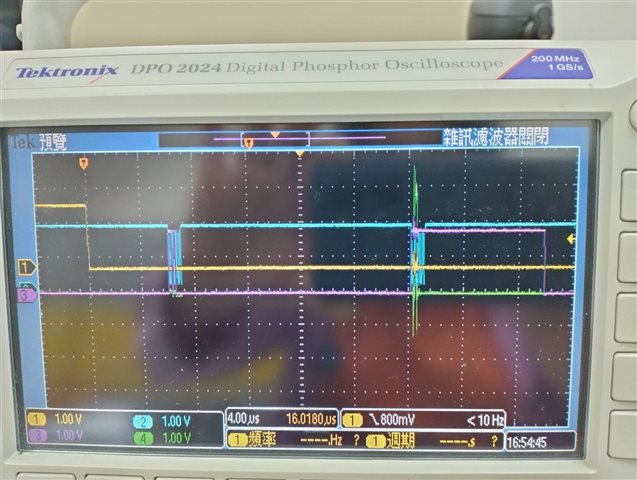
        Solid connection                                     Short(SB11-SB14)

 short (SB11-SB14)     

Parents
  • Hi 

    Have you tried to measure the SPI signals on a scope or logic analyzer to see if you get output as expected? 

    In particular look for the presence of the chip select and clock signals. 

    If you just read out 0 it is typically a sign that something is wrong with the pin configuration or the connection between the DK and the sensor. 

    Best regards
    Torbjørn

  • Hi Ovrebekk

                        I use logic analyzer and Oscilloscope to see the p0.08(SCLK) and p0.11(CS), the result is CS has waveforms and SCLK no any waveforms.The attached file is my overlay and prj.conf for this case, please give any suggestion,Thanks.

    another question is I create *.yaml(zephyr\dts\bindings\sensor)filefor ST-LIS2HH12 sensor, for bmp280 is only create for bosch,bmp280-spi.yaml, but for ST sensor isn't need two yaml?As below ST-LIS2DW example, it need for common and spi two file.

    8255.nrf7002dk_nrf5340_cpuapp.overlay

    0763.prj.conf

    Is this clock and power collides issue reason for no SPI(master) SCLK waveforms?

    For upper collides problem I try to reconfig for "nrf5340_cpuapp_peripherals.dtsi" file.For this file at starting(power collides with clock), (kmu collides with flash-controller) I modified as attached file, after modified the build result failed as below, how to modify for these resource address not collides at the same time build success and work?

    [93/150] Building C object zephyr/CMakeFiles/zephyr.dir/soc/arm/nordic_nrf/validate_base_addresses.c.obj
    FAILED: zephyr/CMakeFiles/zephyr.dir/soc/arm/nordic_nrf/validate_base_addresses.c.obj
    C:\ncs\toolchains\c57af46cb7\opt\zephyr-sdk\arm-zephyr-eabi\bin\arm-zephyr-eabi-gcc.exe -DKERNEL -DNRF5340_XXAA_APPLICATION -DNRF_SKIP_FICR_NS_COPY_TO_RAM -DPICOLIBC_DOUBLE_PRINTF_SCANF -D_FORTIFY_SOURCE=1 -D_POSIX_C_SOURCE=200809 -D__LINUX_ERRNO_EXTENSIONS__ -D__PROGRAM_START -D__ZEPHYR__=1 -IC:/ncs/v2.5.2/zephyr/kernel/include -IC:/ncs/v2.5.2/zephyr/arch/arm/include -IC:/ncs/v2.5.2/zephyr/include -Izephyr/include/generated -IC:/ncs/v2.5.2/zephyr/soc/arm/nordic_nrf/nrf53 -IC:/ncs/v2.5.2/zephyr/soc/arm/nordic_nrf/common/. -IC:/ncs/v2.5.2/nrf/include -IC:/ncs/v2.5.2/nrf/tests/include -IC:/ncs/v2.5.2/modules/hal/cmsis/CMSIS/Core/Include -IC:/ncs/v2.5.2/zephyr/modules/cmsis/. -IC:/ncs/v2.5.2/modules/hal/nordic/nrfx -IC:/ncs/v2.5.2/modules/hal/nordic/nrfx/drivers/include -IC:/ncs/v2.5.2/modules/hal/nordic/nrfx/mdk -IC:/ncs/v2.5.2/zephyr/modules/hal_nordic/nrfx/. -isystem C:/ncs/v2.5.2/nrfxlib/crypto/nrf_cc312_platform/include -fno-strict-aliasing -Os -imacros C:/ncs/ncs-inter/JMEX_SPI_STM_LIS2HH12/build_SPI_STM_LIS2HH12/zephyr/include/generated/autoconf.h -fno-common -g -gdwarf-4 -fdiagnostics-color=always -mcpu=cortex-m33 -mthumb -mabi=aapcs -mfp16-format=ieee --sysroot=C:/ncs/toolchains/c57af46cb7/opt/zephyr-sdk/arm-zephyr-eabi/arm-zephyr-eabi -imacros C:/ncs/v2.5.2/zephyr/include/zephyr/toolchain/zephyr_stdint.h -Wall -Wformat -Wformat-security -Wno-format-zero-length -Wno-pointer-sign -Wpointer-arith -Wexpansion-to-defined -Wno-unused-but-set-variable -Werror=implicit-int -fno-pic -fno-pie -fno-asynchronous-unwind-tables -ftls-model=local-exec -fno-reorder-functions --param=min-pagesize=0 -fno-defer-pop -fmacro-prefix-map=C:/ncs/ncs-inter/JMEX_SPI_STM_LIS2HH12=CMAKE_SOURCE_DIR -fmacro-prefix-map=C:/ncs/v2.5.2/zephyr=ZEPHYR_BASE -fmacro-prefix-map=C:/ncs/v2.5.2=WEST_TOPDIR -ffunction-sections -fdata-sections --specs=picolibc.specs -std=c99 -MD -MT zephyr/CMakeFiles/zephyr.dir/soc/arm/nordic_nrf/validate_base_addresses.c.obj -MF zephyr\CMakeFiles\zephyr.dir\soc\arm\nordic_nrf\validate_base_addresses.c.obj.d -o zephyr/CMakeFiles/zephyr.dir/soc/arm/nordic_nrf/validate_base_addresses.c.obj -c C:/ncs/v2.5.2/zephyr/soc/arm/nordic_nrf/validate_base_addresses.c
    In file included from C:/ncs/v2.5.2/zephyr/include/zephyr/toolchain.h:50,
    from C:/ncs/v2.5.2/zephyr/include/zephyr/kernel_includes.h:19,
    from C:/ncs/v2.5.2/zephyr/include/zephyr/kernel.h:17,
    from C:/ncs/v2.5.2/zephyr/soc/arm/nordic_nrf/validate_base_addresses.c:7:
    C:/ncs/v2.5.2/zephyr/include/zephyr/toolchain/gcc.h:81:36: error: static assertion failed: ""
    81 | #define BUILD_ASSERT(EXPR, MSG...) _Static_assert(EXPR, "" MSG)
    | ^~~~~~~~~~~~~~
    C:/ncs/v2.5.2/zephyr/soc/arm/nordic_nrf/validate_base_addresses.c:87:9: note: in expansion of macro 'BUILD_ASSERT'
    87 | BUILD_ASSERT( \
    | ^~~~~~~~~~~~
    C:/ncs/v2.5.2/zephyr/soc/arm/nordic_nrf/validate_base_addresses.c:140:1: note: in expansion of macro 'CHECK_DT_REG'
    140 | CHECK_DT_REG(flash_controller, NRF_NVMC);
    | ^~~~~~~~~~~~
    C:/ncs/v2.5.2/zephyr/include/zephyr/toolchain/gcc.h:81:36: error: static assertion failed: ""
    81 | #define BUILD_ASSERT(EXPR, MSG...) _Static_assert(EXPR, "" MSG)
    | ^~~~~~~~~~~~~~
    C:/ncs/v2.5.2/zephyr/soc/arm/nordic_nrf/validate_base_addresses.c:87:9: note: in expansion of macro 'BUILD_ASSERT'
    87 | BUILD_ASSERT( \
    | ^~~~~~~~~~~~
    C:/ncs/v2.5.2/zephyr/soc/arm/nordic_nrf/validate_base_addresses.c:157:1: note: in expansion of macro 'CHECK_DT_REG'
    157 | CHECK_DT_REG(power, NRF_POWER);
    | ^~~~~~~~~~~~
    C:/ncs/v2.5.2/zephyr/include/zephyr/toolchain/gcc.h:81:36: error: static assertion failed: ""
    81 | #define BUILD_ASSERT(EXPR, MSG...) _Static_assert(EXPR, "" MSG)
    | ^~~~~~~~~~~~~~
    C:/ncs/v2.5.2/zephyr/soc/arm/nordic_nrf/validate_base_addresses.c:87:9: note: in expansion of macro 'BUILD_ASSERT'
    87 | BUILD_ASSERT( \
    | ^~~~~~~~~~~~
    C:/ncs/v2.5.2/zephyr/soc/arm/nordic_nrf/validate_base_addresses.c:168:1: note: in expansion of macro 'CHECK_DT_REG'
    168 | CHECK_DT_REG(reset, NRF_RESET);
    | ^~~~~~~~~~~~
    [102/150] Building C object zephyr/drivers/spi/CMakeFiles/drivers__spi.dir/spi_nrfx_spim.c.obj
    ninja: build stopped: subcommand failed.
    FATAL ERROR: command exited with status 1: 'C:\ncs\toolchains\c57af46cb7\opt\bin\cmake.EXE' --build 'c:\ncs\ncs-inter\JMEX_SPI_STM_LIS2HH12\build_SPI_STM_LIS2HH12'

    * The terminal process terminated with exit code: 1.
    * Terminal will be reused by tasks, press any key to close it.

    4478.nrf5340_cpuapp_peripherals.dtsi

    Best Regards

       Tina

  • Hi Tina

    Sorry for the slow response, I was on travel last week. 

    Regarding P0.08 and P0.11 these pins are used for the external memory interface, as described here. I expect this is the reason you can't properly enable them. 

    Have you tried to use SPI1 instead, which is assigned to the Arduino SPI pins (P1.12-P1.15) ? 

    yithwe said:
    another question is I create *.yaml(zephyr\dts\bindings\sensor)filefor ST-LIS2HH12 sensor, for bmp280 is only create for bosch,bmp280-spi.yaml, but for ST sensor isn't need two yaml?

    If you want the same sensor driver to support both I2C and SPI, selected directly from the device tree, you need separate binding files for this. If you are making your own driver I would suggest just making a single binding, depending on which interface you are planning to use (SPI or I2C). 

    yithwe said:
    Is this clock and power collides issue reason for no SPI(master) SCLK waveforms?

    No, I don't think this is the issue. There should be no need to modify the power or clock nodes in the device tree to use SPI. 

    Best regards
    Torbjørn

  • Hi Ovrebekk

                 Thanks for your reply.

                        Regarding P0.08 and P0.11 these pins are used for the external memory interface, as described here. I expect this is the reason you can't properly enable them. 

    For this external memory issue, I try to short SB11~SB14 and remove external memory IC from nRF7002-Dk board, frequency set as 8MHz and use SPI mode 3. For ST Lis2HH122 sensor read result is 0x00 or 0xFF,no any write result.

    But For BME280 sensor can read chip ID, but the read result is fault(it's mismatch with data sheet value), write result is not stable.

    I use Exercise1 for this issue.

    Have you tried to use SPI1 instead, which is assigned to the Arduino SPI pins (P1.12-P1.15) ? 

    I try to use P0.06 P0.07 P0.25 P0.26 for SPI mode3,the result is same as upper for BME280 and ST Lis2HH122 sensor.

    Another question (1) is I want to use SPI mode 3 (CPOL=1,CPHA=1) for this exercise.can I use below setting for spi operation as below?

    #define SPIOP   SPI_WORD_SET(8) | SPI_TRANSFER_MSB | SPI_MODE_CPOL | SPI_MODE_CPHA
     
    Another question (2) zephyr RTOS need for nRF7002-DK, isn't it? Is RTOS scheduling effect for SPI read write respone time?
    Below attached picture have two issue will effect for read respone time 
    1.After cs active low(yellow line) it need 6us wait and the first spi clock start(blue line) 
    2.Read sensor BME280 register over the spi with frequency 8MHz, SPI mode 3 (CPOL=1,CPHA=1), the respone time is over 16us
    For this two issue do you have any suggestion for decrease respone time?
    4/17 Another question(3)
    Setting SPI pin duration time and GPIO pin setting as high drive can solve this problem?
    How to setting duration time for SPI pin when use zephyr driver?
    We need transmit data high bit for long time(with limit delay time), so this issue will be buttolneck for our application. If any we need to precaution, please don't hestiate for give advice, many thank.
      

     Best Regards 

         Tina

Reply
  • Hi Ovrebekk

                 Thanks for your reply.

                        Regarding P0.08 and P0.11 these pins are used for the external memory interface, as described here. I expect this is the reason you can't properly enable them. 

    For this external memory issue, I try to short SB11~SB14 and remove external memory IC from nRF7002-Dk board, frequency set as 8MHz and use SPI mode 3. For ST Lis2HH122 sensor read result is 0x00 or 0xFF,no any write result.

    But For BME280 sensor can read chip ID, but the read result is fault(it's mismatch with data sheet value), write result is not stable.

    I use Exercise1 for this issue.

    Have you tried to use SPI1 instead, which is assigned to the Arduino SPI pins (P1.12-P1.15) ? 

    I try to use P0.06 P0.07 P0.25 P0.26 for SPI mode3,the result is same as upper for BME280 and ST Lis2HH122 sensor.

    Another question (1) is I want to use SPI mode 3 (CPOL=1,CPHA=1) for this exercise.can I use below setting for spi operation as below?

    #define SPIOP   SPI_WORD_SET(8) | SPI_TRANSFER_MSB | SPI_MODE_CPOL | SPI_MODE_CPHA
     
    Another question (2) zephyr RTOS need for nRF7002-DK, isn't it? Is RTOS scheduling effect for SPI read write respone time?
    Below attached picture have two issue will effect for read respone time 
    1.After cs active low(yellow line) it need 6us wait and the first spi clock start(blue line) 
    2.Read sensor BME280 register over the spi with frequency 8MHz, SPI mode 3 (CPOL=1,CPHA=1), the respone time is over 16us
    For this two issue do you have any suggestion for decrease respone time?
    4/17 Another question(3)
    Setting SPI pin duration time and GPIO pin setting as high drive can solve this problem?
    How to setting duration time for SPI pin when use zephyr driver?
    We need transmit data high bit for long time(with limit delay time), so this issue will be buttolneck for our application. If any we need to precaution, please don't hestiate for give advice, many thank.
      

     Best Regards 

         Tina

Children
  • Hi Tina

    1) As far as I can tell you have enabled SPI mode 3 the correct way, yes. Did you verify on the scope if the clock and MOSI lines are updated as expected? 

    2) The Zephyr kernel will run under the hood, yes. 

    The SPI timing is mostly affected by the efficiency of the driver, more than the use of Zephyr itself. 16us between bytes does seem a bit high.

    Do you know which part of the driver code handles this transaction? 

    Longer SPI transactions are much more efficient as they allow the SPI peripheral to send bytes back to back, while if you only send single bytes from the driver side there will be some gap between them in order to handle peripheral interrupts etc. 

    3) One of my colleagues discussed the issue of too long delay between CSN going low and the data being output in this case

    Essentially possible workarounds is to either switch to spi4, and/or use the nrfx_spim driver for more direct control of the SPIM peripheral. Please note that using nrfx directly means you would not be able to use higher level sensor drivers, so this might not be a good option in your case. 

    Using high drive might reduce fall/rise times of your signals, but won't speed up the timing overall. 

    Best regards
    Torbjørn

Related