Not able to read SPI and COM PORT access denied

Hi,

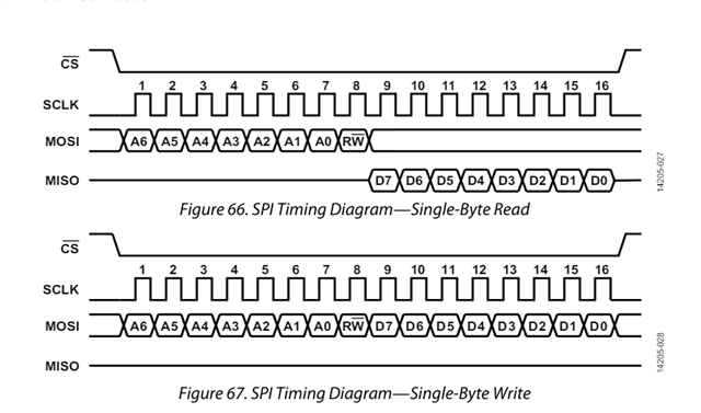
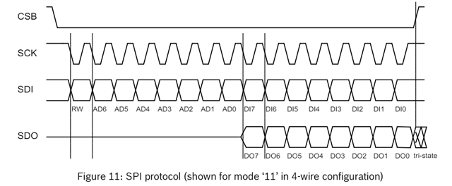
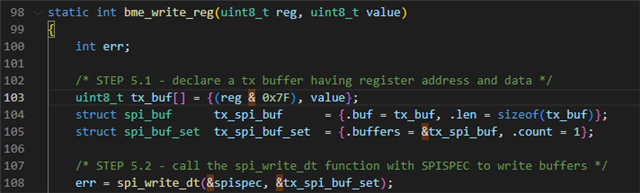
I am developing an application to read the ADXL355 via SPI. I have not been able to read the register of my accelerometer. And I don't know why. 
I tried reading the register of the device ID, but I still got 0. Maybe it is a hardware problem.
I built the application and suddenly I was not able to print messages to the port anymore "COM3: Access denied".
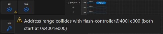
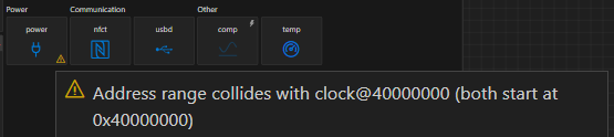
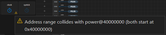
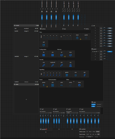
I checked the device tree file and I see this messages, I am not sure if these are the cause of not being able to read the registers and of the com port error:


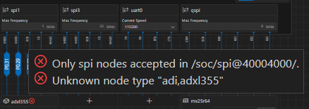
I will also add a zip file of my project in case it is useful.

2664.SPITry9.zip

Thank you very much.

Adrián Lopez Vudoyra.

---------------------------------------------------------------------

Edit, I restarted the computer and the COM Port works now. I am still not able to read the registers. I tried reseting the device first and then reading, but it is still not returning anything. I thought of it being a hardware problem, but wouldn't it return an error at some point in the init()?

Parents
  • Hi,

    First, 0x40000.... means that this peripheral has not been enabled for NS (non secure) variant, you should get CPU crash in this case.

    Would suggest starting with existing driver such as ADXL362 (read and verify the ID).

    Also read the raw value from SPI read, if you get 0xFF, then something wrong with the SPI read itself, try lowering SPI clock.

    Can you physically trace SPI signals ?

    Lastly, not entirely sure using `printk` inside the driver is a good idea.

    Thanks,
    Reuven

  • Hi Reuven,

    Thank you so much for your answer. 

    peripheral has not been enabled for NS (non secure) variant, you should get CPU crash

    Where should I be getting the CPU crash here? Because in my program everything proceeds as normal, it just prints 0x00.

    lso read the raw value from SPI read, if you get 0xFF

    I tried debugging the init function, I am getting 0x00 as a value. In all of the registers that I have tried to read.

    Can you physically trace SPI signals ?

    I saw in the Lesson 5 exercise 1 of the intermediate ncs SDK that there was a tool to do so, but they did not say the name. Which tool would you recommend me? Do I need a tool(Multimeter)? Or can I do it directly with my computer?

    not entirely sure using `printk`

    Would it be better if I used LOGINF then? I used printk because it is being used in the Lesson7 exercise 1 of the same course previously mentioned

    Thank you very much. 

    Adrian Lopez Vudoyra

  • Adrian1504 said:
    I saw in the Lesson 5 exercise 1 of the intermediate ncs SDK that there was a tool to do so, but they did not say the name

    We used Saleae Logic Analyzer for that, but we cannot recommend our customers for any specific vendor. Also, different such products should be available in the market.

    How does your hardware look like? Yes, mostly it is a bad / incorrect / loose connection or a hardware issue.

Reply Children
  • Hi Naeem,

    Thank you, I still haven't been able to use a logic analyzer, but I did get other accelerometer and its still not working.

    After I try to read the DEVICE_ID register, my receiver buffer looks like this:
    rx_buffer[255,173,29]

    It does not change, it doesent matter the register that I send. 

    This is the function I am using:

    int spi_test(const struct device *dev)
    {
    	const struct custom_adxl355_config *cfg = dev->config;
    
    	static uint8_t tx_buffer[3];
    	static uint8_t rx_buffer[3];
    
    	const struct spi_buf tx_buf = {
    		.buf = tx_buffer,
    		.len = sizeof(tx_buffer)
    	};
    	const struct spi_buf_set tx = {
    		.buffers = &tx_buf,
    		.count = 1
    	};
    
    	struct spi_buf rx_buf = {
    		.buf = rx_buffer,
    		.len = sizeof(rx_buffer),
    	};
    	const struct spi_buf_set rx = {
    		.buffers = &rx_buf,
    		.count = 1
    	};
    
    
    	/*
    	first 2 bytes of tx specify read/write action and on which register to perform
    	last byte of rx contains the respons from the accelerometer
    	*/
    
    	tx_buffer[0] = ADXL355_SPI_READ;
    	tx_buffer[1] = ADXL355_ADDR(ADXL355_DEVID_MST);
    
    	int error = spi_transceive_dt(&cfg->spi, &tx, &rx);
    	if(error != 0){
    		printk("SPI transceive error: %i\n", error);
    		return error;
    	}
    
    	uint8_t x = rx_buffer[2];
    	if(ADXL355_PARTID == rx_buffer[2])
    	{
    		printk("Successfull ACC communication\n");
    	}
    	else
    	{
    		printk("Faild ACC communication\n");
    	}
    
    	return 0;
    }

    I really don't know what could be going wrong.

    I add the zip file of with my modifications in case it is useful.
    ADXL355Try2.zip

    Thank you for your time.

    Adrian Lopez Vudoyra

  • It might be possible that you configured the pins wrong. But to be able to have a proper debugging direction for this, you still need either a logic analyzer or similar or atleast an oscilloscope to see if the clock and data pins are transcieving anything. If there is not activity on the data pins, then we can focus on the pin configuration. If there is activity and proper data on the pins, then we can see how this data is handled by the SPI driver and the ADXL355 driver. Right now we do not have proper direction without you showing us what is being transmitted on the pins.

  • Hi Susheel,

    Thank you so much for your reply. I will try to get an oscilloscope or a Logic Analyzer and post the results so that we can continue with this debugging. 


    I was going through the datasheet (SPI diagrams) of the BME280 from the intermediate course and compared a little with the datasheet from the ADXL355. I noticed that the R/W bit for the ADXL355 goes in the end:

    ADXL355:

    BME280:


    Should I modify something in my program with this?

    Thank you.

    Adrian Lopez Vudoyra

  • Hi Adrian,

    Thank you for going through the datasheets and making comparisons.

    Yes, indeed, that would be the case and you will have to update the code accordingly.

    For example, (BME Example from the intermediate course),

    you can see that for writing, the 8th bit [b7 from b7...b0] is set as 0 in line 103 while for reading it is left 1.

    So yes, please make suitable changes as per your own sensor and datasheet.

    Regards,
    Naeem

  • Hi Naeem,

    Thank you so much for your answer!

    So for me it would have to be tx_buf[] = {(0x00 & reg),value}, right?

    And for reading tx_buffer & (void *)?

    Thank you,

    Adrian Lopez Vudoyra

Related