case about nRF9160 example serial_lte_modem GPIO_AT_commands about P0.26 P0.27

Hi,

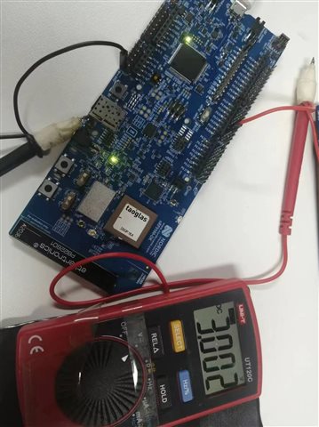
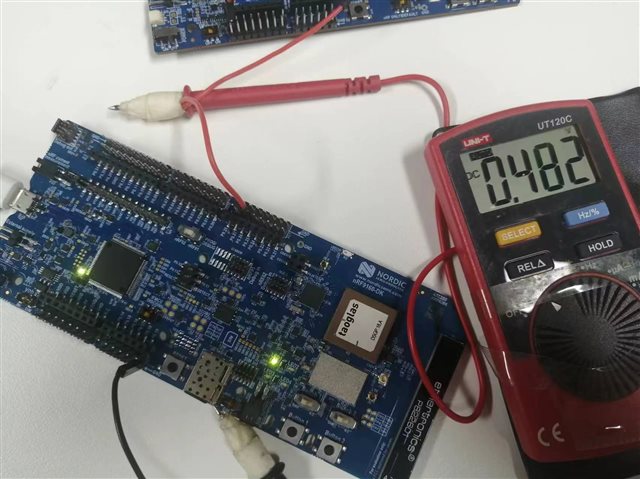
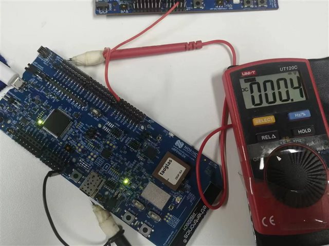
1. In ncs v2.6.0 example serial_lte_modem, the level of the P0.26 P0.27 I/O port on the PCA10090 DK board is measurement  0V or 0.8V . Set the high level, normal should equal the VDD voltage 3.0V ,What causes the inconsistent external measurement voltage after the AT instruction is set here?

2. The following changes were made: Cut DK slats SB11 SB12 To modify the serial_lte_modem routine, remove the RTC CTS port with port P0.27P0.27 as the serial port, and disable serial flow control.

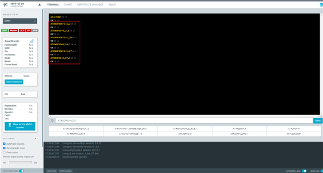
3. The command is as follows:


AT#XGPIOCFG=1,26
AT#XGPIOCFG=1,27
AT#XGPIO=0,26,1
AT#XGPIO=0,27,1

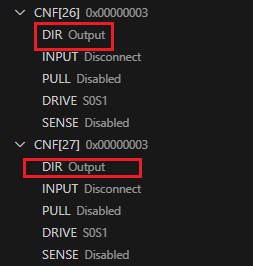
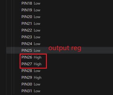
4.debug View the configuration of the GPIO0 register as follows:

Thank you for all your assistance.
Kind regards,
Peter.Min

  • Hi,

    How did you disable the HW flow control?

    And are you sure the solder bridges are completely cut?

    Have you tried to use other pins that are not sed for anything else on the DK, do you get the expected voltage on those?

    Best regards,

    Didrik

  • Hi Didrik Rokhaug,

    1.disabled HW like :

    /*
     * Copyright (c) 2021 Nordic Semiconductor ASA
     *
     * SPDX-License-Identifier: LicenseRef-Nordic-5-Clause
     */
    
    / {
    	chosen {
    		ncs,slm-uart = &uart0;
    	};
    };
    
    &uart0 {
    	status = "okay";
    	current-speed = <115200>;
    	pinctrl-0 = <&uart0_default>;
    	pinctrl-1 = <&uart0_sleep>;
    	pinctrl-names = "default", "sleep";
    	/delete-property/ hw-flow-control;
    	/delete-property/ rts-pin;
    	/delete-property/ cts-pin;
    };
    
    /*
    &uart0 {
    	status = "okay";
    };
    */
    
    &uart2 {
    	compatible = "nordic,nrf-uarte";
    	current-speed = <115200>;
    	status = "disabled";
    	hw-flow-control;
    
    	pinctrl-0 = <&uart2_default_alt>;
    	pinctrl-1 = <&uart2_sleep_alt>;
    	pinctrl-names = "default", "sleep";
    };
    
    &i2c2 {
    	status = "disabled";
    };
    
    &pinctrl {
    	uart0_default: uart0_default {
    		group1 {
    			psels = <NRF_PSEL(UART_TX, 0, 29)>;
    		};
    		group2 {
    			psels = <NRF_PSEL(UART_RX, 0, 28)>;
    			bias-pull-up;
    		};
    	};
    
    	uart0_sleep: uart0_sleep {
    		group1 {
    			psels = <NRF_PSEL(UART_TX, 0, 29)>,
    				<NRF_PSEL(UART_RX, 0, 28)>;
    			low-power-enable;
    		};
    	};
    	uart2_default_alt: uart2_default_alt {
    		group1 {
    			psels = <NRF_PSEL(UART_RX, 0, 11)>;
    			bias-pull-up;
    		};
    		group2 {
    			psels = <NRF_PSEL(UART_TX, 0, 10)>,
    				<NRF_PSEL(UART_RTS, 0, 12)>,
    				<NRF_PSEL(UART_CTS, 0, 13)>;
    		};
    	};
    
    	uart2_sleep_alt: uart2_sleep_alt {
    		group1 {
    			psels = <NRF_PSEL(UART_TX, 0, 10)>,
    				<NRF_PSEL(UART_RX, 0, 11)>,
    				<NRF_PSEL(UART_RTS, 0, 12)>,
    				<NRF_PSEL(UART_CTS, 0, 13)>;
    			low-power-enable;
    		};
    	};
    };


    2.cut is ok

    3.LED1-LED4 test ok

    4.code is here

    8814.serial_lte_modem.zip

    Thank you for all your assistance.
    Kind regards,
    Peter.Min

  • How are you meassuring the voltage?

    Do you have something to meassure the voltage over?

    And have you set the VDD_IO switch in the 3V position?

  • Hi Didrik Rokhaug,

    Measured with the DC setting of a multimeter.

    VDD_IO has been switched to 3V.

    The AT instructions are as follows:

    The P0.02 port is measured as follows

    P0.26口测量如下

    P0.27口测量如下

    Thank you for all your assistance.
    Kind regards,
    Peter.Min

  • Just to make sure that there is nothing wrong with the DK, have you tested with other DKs?

Related