Flashing nRF52840 dongle through SWD interface

Dear community,

I'm trying to flash a nRF52840 dongle through the SWD interface, but fail. There are already several nRF52840-dongle flashing posts in the forum, but I obviously misunderstand some of the instructions.

==> does someone see where I go wrong?

Namely, I expect the error to be either in the wiring, and/or how I set the REGOUT0.


First, on the hardware used:

  • nRF52-DK (pca10040),
  • nRF52840-dongle (pca10059)
    (version 2.1.1, manufactured in 2023.19)


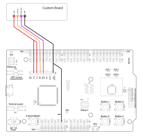
The nRF52-DK, I have wired as described in [1] using the P20 pins:

I'm using this setup already successfully in programing a custom nRF52832 board.


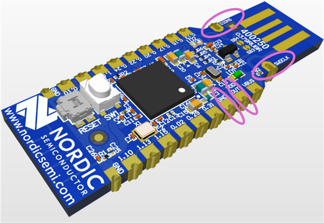
On the nRF52840-dongle, I'm connecting the 4 wires shown in post [2]:

  • GND to GND
  • VDD to "VDD out" (<-- the pin between "GND" and "VBUS")
  • SWD CLK to SWDCLK
  • SWD IO to SWDIO


What works:
`> nrfjprog -f NRF52 --recover`

What does not work:
`> nrfjprog -f NRF52 --program fw.hex --verify`
Error message: the verification finds all memory locations to be 0x00 instead of populated with values (in other words, nothing is actually programmed).


First question:
Am I right in connecting the "VDD OUT" pin on the nRF52840-dongle (like in [2])?
Note, I did not cut/bridge SB1/2 [3], because in the end, I want to use the USB 5V supply. I only want to use the external 3V while flashing. Or is this not possible? From how I understand the answer in [4], modifying the SB1/2 is only need when working without an external debugger with level shifter -- which, I understand, the nRF52-DK does provide?


Second question:
The "nRF52840-dongle programming tutorial" [5] mentions that (one should avoid a full `--recover`, and that) the REGOUT0 must be set before programming a new hex-file.

==> what should I set REGOUT0 to?


What I've tried:
`> nrfjprog -f NRF52 --recover`
`> nrfjprog -f NFR52 --memwr 0x10001304 --val 4`
`> nrfjprog -f NRF52 --program fw.hex --verify`

Result: still all 0x00 values.

  • Do I access the correct register at 0x10001304?
  • Is "--val 4" the right value? (The voltage on the VDD pin of the nRF52-DK is indeed 3.0V.)


When I `nrfjprog --memrd 0x10001304` (or `nrfjprog --readuicr`), I can confirm that 0x10001304 is set to 00000004.


Thank you very much,
Stefan


[1] Programming custom NRF52832 board using SWD interface 
[2] nRF52840 Dongle swd flashing 
[3] https://infocenter.nordicsemi.com/index.jsp?topic=%2Fug_nrf52840_dongle%2FUG%2Fnrf52840_Dongle%2Fhw_power_ext_reg_source.html&cp=3_0_5_5_2_1
[4] trouble flashing nRF52840 Dongle with non-example code 
[5] nRF52840 Dongle Programming Tutorial 

  • Hello,

    When you execture --recover or --eraseall, then UICR is erased, and VDD will switch to (default) 1.8V, this is lower than what the nRF52-DK can program. You will need to follow description in  nRF52840 Dongle Programming Tutorial  :

    Recover after an accidental UICR erase

    You have two options for recovering when the REG0 (VDD) voltage is 1.8 V (typically after a UICR erase):

    • Either use a debug probe that adapts the logic levels to the target device (for instance a J-Link PRO). Program firmware that configures REGOUT0 for 3 V.
    • Or modify the dongle so that it can be supplied by an external supply and use the nRF52840 DK to program it.
      1. Adapt the dongle hardware as described under External regulated source in the nRF52840 Dongle documentation.
      2. Connect VDD from the nRF52840 DK to VDD OUT on the nRF52840 Dongle.
      3. Program via SWD as you have previously done (but remember to set REGOUT0 this time).

    To set REGOUT0 correctly follow the Adapting firmware to set REGOUT0 properly on the same page.

    Kenneth

  • Hi Kenneth,

    thank you for your reply.

    Let me try again, this time, please assume I'm a complete beginner with no prior understanding.

    The Dongle Programming Tutorial states

    If you must erase the UICR, make sure that you do not reset the board until after you have programmed either REGOUT0 directly or firmware that sets it.

    Do I understand wrongly that this refers to

    nrfjprog --memwr 0x10001304 ...

    as one of the programming steps?

    Alternatively, how can I flash a firmware (such as stated in the section "Adapting firmware to set REGOUT0 properly") when REGOUT0 is on its default 1.8V setting? I read this as "you need a chicken to lay an egg, but you need an egg to raise a chicken".

    Ok, I can use a J-Link instead of the nRF52-DK.

    ==> do I correctly use "VDD OUT" on the nRF52840-dongle?

    ==> will I have to specify "vtref 3000" for the J-Link, or how will it know to what value to set the logic levels?

    (I ask, because nrfjprog reports that the connection has timed out. Hence, the J-Link cannot establish any connection.)

    Lastly, let's say I take a brand new nRF52840-dongle: how do I actually achieve erasing the whole memory except for REGOUT0? If I don't start with --recover, then there is a memory protection in place.

    Thanks for any clarifications,

    Stefan

  • All the information that is required to program the nRF52840 USB Dongle is in the blog post you refer to. Recovering or Eraseall will allways erase UICR, and the voltage will then fall back to 1.8V as default. The dongle will work wither 1.8V or 3V, the problem you experience is that the nRF52-DK don't support 1.8V for programming, so the blog post describe how you can overcome that (either by feeding the dongle with external voltage or that you get yourself a J-Link programmer that can support the entire supply range).

    My suggestion if you are not able to make the blog post is to either get an nRF52840-DK (it's not going to support 1.8V either, but you can then develop directly on the DK) or that you get yourself a SEGGER J-Link.

    Kenneth

Related