This post is older than 2 years and might not be relevant anymore
More Info: Consider searching for newer posts

Programming custom NRF52832 board using SWD interface

Hello NRF,

I have a custom board with NRF52832, and exposed the SWDIO, SWDCLK, GND, VDD, RESET pins for programming the board through the NRF52-DK board.

I started with a sample peripheral_uart, connected the NRF52-DK board to my PC, and managed to BUILD and RUN the sample application.

I verified that the app is working, by connecting to the UART service advertised by this app (on NRF52-DK) through another device that has NRF-TOOLBOX and used the UART service to query the NRF UART (NRF52-DK board) and managed to read write and verified the same over the console.

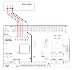
Now, I want to program my custom board, instead of the NRF52-DK board. Based on some suggestions on this site, I connected the

NRF52-DK        CUSTOM_BOARD

SWDIO             SWDIO

SWDCLK          SWDCLK

GND-DET         GND

VTG                 VDD/3V3

I then powered my board and then tried the BUILD and RUN option on the SEGGER.

It seems like my custom board is not getting programmed.

I would like to know : 

1. Do I have to first program a bootloader on to my custom board. If so, please advise a boot loader that I can download from your site (if possible) and the steps to program the same on to my custom board.

2. How to program the compiled/build binary/hex files on to my custom card? Just BUILD and RUN would download the binary on to the connected custom board, instead of the NRF52-DK board? (because my custom board is connected through the SWD port and GND detected?) If BUILD and RUN wouldn't work, where can I find the compiled binary or hex file where I can program the same on to the custom board , perhaps by using command line nrfjprog tool???

3. I believe the peripheral_uart has it's pin definitions, for the RX, TX, LEDs etc. Since my custom board pin assignments might be different from that of the NRF52-DK, where can I find these definitions, so I can go map the pins?

All I need is to demonstrate this peripheral_uart app on my custom nrf52832 board, where I will connect a serial port on to its RX/TX to a putty terminal (on my pc) and then able to rx/tx data back and forth with the other connected device (NRF toolbox -> UART).

I appreciate your help in this regard.

regards,

Dinesh.

  • Hi Dinesh

    Please confirm that your custom device is connected as shown in this picture when trying to program it. How is your custom board powered?

    1. No, you do not need a bootloader, the debugger on the DK will be able to access the Flash of the nRF52 series through the SWD interface.

    2. Yes, when the custom board is connected correctly to the DK, the "Build and Run" command in SES will download the application onto the custom board, as it will detect connected custom boards automatically.

    3. In the peripheral_uart example you can see that the RX and TX pin numbers are defined as RX_PIN_NUMBER and TX_PIN_NUMBER. These are defined in the board file (C:\...\nRF5_SDK_17.0.2_d674dde\components\boards\pca10040.h), and when making a project for a custom board, you should create your own custom_board.h file. This is described in the Infocenter here where it is explained how to use the SDK with custom boards.

    Best regards,

    Simon

  • Hello Simonr,

    I was powering my custom board separately (through a coin cell battery) and wired the VTG on DK to VDD on my board side (3.3v).

    I will remove the power source (coin cell) on my board, and power the custom board through the NRF52-DK as per your suggestion.

    I believe, once I execute the BUILD  & RUN, the same behavior is expected on my custom board, similar to how it runs on the DK, as on DK, I see the NRF advertisements, but when I programmed my board, I couldn't see the advertisements.

    I will test this and get back to you.

    Thanks.

    regards,

    Dinesh.

  • Please let me know whether this is successful or not. If you're still struggling, please let me know some details about your custom board. If you're, for example, lacking an external LF crystal that is likely the issue.

    Best regards,

    Simon

  • Hello Simnor,

    I still struggle with this setup.

    I connected the power/GND/SWDIO/SWDCLK as per your suggestion.

    When I run the BUILD & RUN from the SES, I can see that the programming is going on.

    However, I programmed the unit with the peripheral_uart example, and I expect it to start advertising, and I should be able to use another device with NRF Toolbox -> UART and Connect / Scan , where I expect the unit to pop up with Nordic_UART_Service. But I don't get that. 

    On the  other hand, if I program the NRF52832 on the DK board (by removing my device from the DK), I am able to observe its advertisements with "Nordic_UART_Service".

    I believe for this "periphral_uart" example, no external pins are required for it to kick start the advertisement?

    And, my NRF custom design has an external Crystal connected to it, which is 32MHz.

    Side note, I am able to program a custom bootloader + app on this board, through a set of utilities provided by Sparkfun, The app works fine on this custom board. However, the issue is, the sample app template they have provided and their libs wouldn't let me to obtain the low power levels (around 10 - 20uA) , compared to what your setup seems to support. So I want to use the same hardware and start the development with the SES. Why I am saying this, is to let you know that the custom hardware board is functional (with someone elses tools).

    So I need your support to get my custom hardware to run the uart_peripheral and start advertising, where I can pick up the advertisements from another Android device running NRF Toolbox -> UART.

    A few questions.

    1. Since I already flashed a softdevice + bootloader to these boards (for the sprakfun), does your debugger ignores them and flash the sample app directly and able to run it? (uart_peripheral app from the SES, build and run option)

    2. What other additional requirements are needed to run the perhipheral_uart sample, through SES -> BUILD & RUN option?

    Looking forward to hearing back from you soon.

    regards,

    Dinesh.

  • Hi again Dinesh

    You're using nRFConnect SDK (NCS), correct? And thus this example project? If you only have the one external crystal that explains why it doesn't start advertising. In order to run most of our examples, you also need to use a LF clock (32.768 kHz), and our example projects are configured to use the optional external (XTAL) 32.768kHz crystal. You can configure the example to use the internal RC oscillator instead though, which should make the application run as intended.

    1. NCS does not use the SoftDevices, so it seems like you're mixing up the nRF5 SDK and the nRFConnect SDK.

    2. I believe it should be sufficient to configure the project to use the RC oscillator instead of the XTAL. Please see the documentation here for details. The calibration should be enabled by default when the RC oscillator is enabled it seems.

    Best regards,

    Simon

Related