Hi
I need to send data from nRF7002 to external CPU(STM32) use UART protocol, for HW nRF7002 P0.20 connect STM32 RX and RF7002 P0.22 connect STM32 TX, I try to use exercise to modify send 8 bytes data and recieved from STM32 8 bytes data, there is no any data recieved data from STM32 and nRF7002, isn't I miss some config for this flow?below is my device three overlay and code, please give suggestion for this, Thanks.
&uart0_default {
	group1 {
		psels = <NRF_PSEL(UART_TX, 0, 20)>, <NRF_PSEL(UART_RTS, 0, 19)>;
	};
};

&uart0_sleep {
	group1 {
		psels = <NRF_PSEL(UART_TX, 0, 20)>,
				<NRF_PSEL(UART_RX, 0, 22)>,
				<NRF_PSEL(UART_RTS, 0, 19)>,
				<NRF_PSEL(UART_CTS, 0, 21)>;
	};
};
&uart0 {
	status = "okay";
	current-speed = <115200>;
	pinctrl-0 = <&uart0_default>;
	pinctrl-1 = <&uart0_sleep>;
	pinctrl-names = "default", "sleep";
};
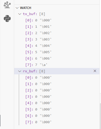
#define RECEIVE_BUFF_SIZE 8
const struct device *uart= DEVICE_DT_GET(DT_NODELABEL(uart0));
static uint8_t tx_buf[] =   {0x00,0x01,0x02,0x03,0x04,0x05,0x06,0x07};
static uint8_t rx_buf[RECEIVE_BUFF_SIZE] = {0};
int main(void)
{
	int ret;
		if (!device_is_ready(uart)){
		printk("UART device not ready\r\n");
		return 1 ;
	}
	ret = uart_tx(uart, tx_buf, sizeof(tx_buf), SYS_FOREVER_MS);
	if (ret) {
		return 1;
	}
		ret = uart_rx_enable(uart ,rx_buf,sizeof rx_buf,RECEIVE_TIMEOUT);
	if (ret) {
		return 1;
	}
	while (1) {
		k_msleep(SLEEP_TIME_MS);
	}
}
Best Regards
Tina