High power consumption of nRF52832 using TWI 100KHz ?

Hi, we are using nRF52832 for our project. SDK version is nRF5_SDK_17.1.0_ddde560. SoftDevice is S132.

The project requires TWI to read data from a sensor and send that data via BLE. The sensor will output 9 bytes every 2.5ms, or 3600B/s data rate. Currently, BLE consumes 0.1mA and it matches the estimated number. When data transfer via BLE is going on, our board consumes 3.8mA. We are trying to lower this number by determining if any part of the system consumes more power than usual.

So we first remove the code that sends data via BLE, which means only connect via BLE, and read data via TWI, but do not send it to the peer. We get a consumption of around 3.2mA
Then we remove the code that reads data from sensor via TWI. This time consumption reduces to 1.5mA. The sensor is still in its working state, just the code to read data in the sensor buffer is removed.

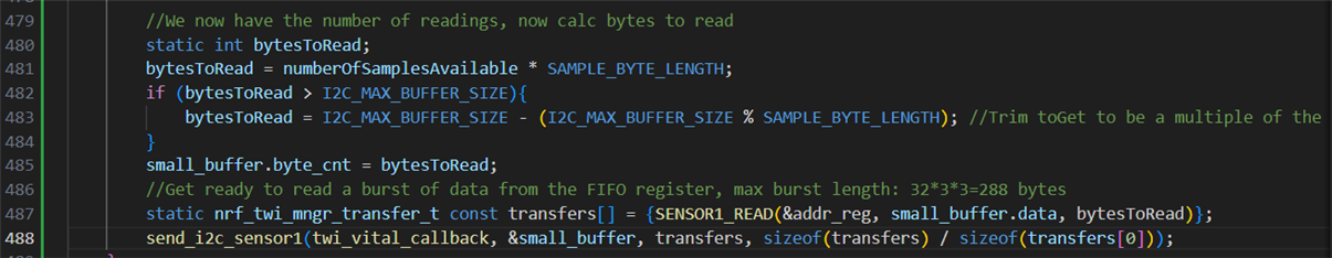
That means reading sensor data via TWI consumes 3.2-1.5=1.7mA. This is so high, especially for a quite low data rate. TWI clock is 100KHz. We check the sensor buffer every 60ms to see if any data is available. The buffer check is simply just 2 registers (head & tail) being read from the sensor. From this, we know how many bytes we can read from the sensor, and we read a burst of that many bytes from the sensor.

Is this number normal for TWI usage? Is there any way we can optimize the power consumption when using TWI? Please let us know soon. We really appreciate your speedy help.

Best regards,

Xander

Parents
  • A handy envelope shows 9 bytes or 81 bits at 100kHz is 810uSec active clock and data in 2500uSec, or about 32%. 32% active I2C data and clock with 4k7 pull-ups on SDA and SCK is (say) 400uA assuming something near 50% duty cycle on both. 1k0 pull ups this would be closer to 1mA, with 10k0 pull-ups closer to 200uA. Test this by switching to more power-efficient 400kHz to see if that part of the power reduces by x4 with the same value pull-ups.

    The key to the balance of power is likely to be "TWI"; TWI is inefficient since the CPU is awake more frequently. TWIM using DMA is much better, maybe approaching 9 times better, as although the same number of bytes are processed the 9 sleep/wakeup cycles and interrupt entry/exit cycles (power consumption overhead) are replaced by a single sleep/wakeup cycle and interrupt, particularly when errata workarounds are in effect. That means 9-byte TWIM, not 9 x 1-byte TWIM; 9 x 1-byte TWIM is even worse than 9 x 1-byte TWI and yes that is commonly used.

    Want optimum efficiency? Switch to SPIM (SPI with DMA), should that be an option, which does not require power-hungry pull-ups. I2C/TWI is old-school from the days when power consumption by other components was orders of magnitude higher; yes it's easy but no it's not a low-power solution. Data processing overhead for TWIM and SPIM both with DMA is similar.

  • Test this by switching to more power-efficient 400kHz to see if that part of the power reduces by x4 with the same value pull-ups.

    Yes it does. I changed to TWI at 400KHz and reading sensor data consumes 0.4mA instead of 1.7mA. I still don't understand why it can be this high?

  • 8-bit TWI isn't; it's 9-bit; there is an ACK bit after every 8-bit byte, and 9x9=81 bits. "Data received will be stored in RAM at the address specified in the RXD.PTR register. The TWI master will generate an ACK after all but the last byte received from the slave. The TWI master will generate a NACK after the last byte received to indicate that the read sequence shall stop"

    30k is an unlikely high value for a TWI/I2C/TWIM pull-up; try measuring it and see if that is the actual value.

    DMA with TWI aka TWIM is trivial, and no, fancy stuff is not required. Start with this bare-metal sample and set the number of received bytes to something larger than 1, such as 9 or higher. i2c_master/main.c

    0.4mA instead of 1.7mA? Either the CPU is not staying in sleep or the 30k pull-ups are 3k0 or so. Quite often the CPU is not staying in sleep, and that's another whole can of worms.

  • I have the PCB schematic and we place the PCB assembly from a fab so it shouldn't be wrong, however, I will contact the PCB designer team to confirm if the schematic I'm having is correct. And it is 50K, not even 30K.

    The resistor size is too small, 0201, and I don't have a probe that can measure the resistance of this tiny thing.

    If the CPU isn't staying in sleep, I think it should use a few mA of consumption, and increasing the TWI clock won't reduce 4x the consumption like this, right?

  • 50k pull-up is highly unlikely to work at all at 400kHz, and would be most doubtful at 100kHz with potential failures in the field, unless the nRF52832 internal 13k pull-up is enabled. As an aside, no designer would choose 50k for an I2C/TWI pull-up; 50k sounds more like a push-button, sensor enable pin or reset pin pull-up value.

    The sleep issue may be that the CPU stays awake for the 9 TWI transfers but sleeps outside that time; just a guess. Predicting code issues is difficult unless you post some of the code, or indeed the schematic.

  • I asked my PCB design team and because of the tiny PCB size, from the simulation with 400KHz I2C, they claim they can go up to 500K ohm pull-up if I want.
    From the firmware side, I don't explicitly pull up any I2C pin.

    Sure below is the code involved in the TWI transfer with sensors.

    Firstly, this is the timer handler that is triggered every 60ms

    static void poll_sensor_timeout_handler(void *p_context){
        UNUSED_PARAMETER(p_context);
        // clear buffer
        for (int i = 0; i < I2C_MAX_BUFFER_SIZE; i++) {
            sensor_data[i] = 0;
        }
        // read data from sensor
        package_len = sensor_checkNewData();
        // send data via BLE to smartphone
        if (package_len > 0){
            ble_data_char_update(sensor_data);
        }
    }

    Here is the code that read sensor data via TWI.

    uint16_t sensor_checkNewData(){
        static sensor_reg addr_reg  = sensor_FIFODATA;
        // static uint8_t data_reg[I2C_MAX_BUFFER_SIZE];
        uint8_t readPointer = sensor_getReadPointer();
        uint8_t writePointer = sensor_getWritePointer();
    
        int numberOfSamplesAvailable = 0;
        
        // new data available when FIFO isn't full (readP # writeP) or when (readP = writeP && A_FULL_INT = high)
        if (readPointer != writePointer || ((readPointer = writePointer) && sensor_getINT_A_FULL())){
            int return_byte = 0;
            //Calculate the number of readings we need to get from sensor
            numberOfSamplesAvailable = writePointer - readPointer;
            if (numberOfSamplesAvailable < 0) numberOfSamplesAvailable += 32; //Wrap condition
    
            //We now have the number of readings, now calc bytes to read
            int bytesToRead = numberOfSamplesAvailable * activeDevices * 3;    
            if (numberOfSamplesAvailable > sample_count_per_MTU)
                {
                    //If bytesToRead is 32 this is bad because we read 6 bytes at a time
                    //32 % 6 = 2 left over. We don't want to request 32 bytes, we want to request 30.
                    //32 % 9 (Red+IR+ECG) = 5 left over. We want to request 27.
    
                    bytesToRead = sample_count_per_MTU * SAMPLE_BYTE_LENGTH;
                }
            return_byte = bytesToRead;
            //Get ready to read a burst of data from the FIFO register, max burst length: 32*3*3=288 bytes
            nrf_twi_mngr_transfer_t const transfers[] = {sensor_READ(&addr_reg, sensor_data, bytesToRead)};
            nrf_twi_mngr_perform(sensor_p_nrf_twi_mngr, sensor_p_twi_config, transfers, 2, NULL);
            return return_byte;
        } else {
            return 0;
        }
    }

    Below are functions that read read/write pointer of sensor internal buffer

    uint8_t sensor_getWritePointer(){
        static sensor_reg addr_reg  = sensor_FIFOWRITEPTR;
        static uint8_t data_reg = 0;
        sensor_read_8(&addr_reg, &data_reg);
        return data_reg;
    }
    
    uint8_t sensor_getReadPointer(){
        static sensor_reg addr_reg  = sensor_FIFOREADPTR;
        static uint8_t data_reg = 0;
        sensor_read_8(&addr_reg, &data_reg);
        return data_reg;
    }

    sensor_read_8 is a helper function to read a single 8-bit register from the sensor

    /**
     * @brief Macro for creating a read transfer from sensor.
     *
     * @param[in] p_reg_addr Pointer to the address of register to read from.
     * @param[in] p_buffer   Pointer to store the read data
     * @param[in] byte_cnt   How many byte to read
     */
    #define sensor_READ(p_reg_addr, p_buffer, byte_cnt) \
        NRF_TWI_MNGR_WRITE(sensor_ADDRESS, p_reg_addr, 1,        NRF_TWI_MNGR_NO_STOP), \
        NRF_TWI_MNGR_READ (sensor_ADDRESS, p_buffer,   byte_cnt, 0)
    
    void sensor_read_8(sensor_reg *p_reg_addr, uint8_t *p_buffer){
        nrf_twi_mngr_transfer_t const transfers[] = {sensor_READ(p_reg_addr, p_buffer, 1)};
        nrf_twi_mngr_perform(sensor_p_nrf_twi_mngr, sensor_p_twi_config, transfers, 2, NULL);
    }
    

    Below is the TWI settings in main.c

    #define TWI_INSTANCE_ID 0
    #define MAX_PENDING_TRANSACTIONS 5
    NRF_TWI_MNGR_DEF(m_nrf_twi_mngr, MAX_PENDING_TRANSACTIONS, TWI_INSTANCE_ID);
    nrf_drv_twi_config_t const twi_config = {
        .scl                = I2C_SCL_PIN,
        .sda                = I2C_SDA_PIN,
        .frequency          = NRF_DRV_TWI_FREQ_400K,
        .interrupt_priority = APP_IRQ_PRIORITY_LOW_MID,
        .clear_bus_init     = false
    };

  • The code you list shows that there is no sleep until the separate TWI transfers complete so as I suggested "The sleep issue may be that the CPU stays awake for the 9 TWI transfers but sleeps outside that time" explaining the cause of the high current and why it reduces when using 400kHz. Switch to TWIM; search the devzone for an example, I see one here twim-errata-109 but there may be better examples; I don't have time to search, perhaps a Nordic engineer could suggest one.

    I2C/TWI/TWIM has a specification Tr which is the rise time of the clock signal SCK; this may be quoted in the datasheet or inferred from (Tclock-(Thigh+Tlow))/2 = Tr = Tf. You don't mention the part number, but Tr is typically 300nSec but may be significantly shorter. Pin capacitance of the nRF52832 is some 3pF, sensor say 3pF also and some distributed capacitance traces and pins to GND giving a minimum 10pF or so. 50k and 10pF violates Tr and may lead to failures in the field, 500k would clearly be unusable. On one battery management IC in a recent design with a short Tr the only way to satisfy Tr was to use a pull-up of 910 Ohm. For a medical or safety device a failure caused by a known Tr or other violation could lead to legal action against the designerin the event of equipment malfunction

    For lowest power in extreme cases, should that be the goal, a simple bare-metal design would minimise CPU on time further; keep in mind nRFx examples are designed to protect the novice user from doing things wrong during development and are not really targeted for final designs.

Reply
  • The code you list shows that there is no sleep until the separate TWI transfers complete so as I suggested "The sleep issue may be that the CPU stays awake for the 9 TWI transfers but sleeps outside that time" explaining the cause of the high current and why it reduces when using 400kHz. Switch to TWIM; search the devzone for an example, I see one here twim-errata-109 but there may be better examples; I don't have time to search, perhaps a Nordic engineer could suggest one.

    I2C/TWI/TWIM has a specification Tr which is the rise time of the clock signal SCK; this may be quoted in the datasheet or inferred from (Tclock-(Thigh+Tlow))/2 = Tr = Tf. You don't mention the part number, but Tr is typically 300nSec but may be significantly shorter. Pin capacitance of the nRF52832 is some 3pF, sensor say 3pF also and some distributed capacitance traces and pins to GND giving a minimum 10pF or so. 50k and 10pF violates Tr and may lead to failures in the field, 500k would clearly be unusable. On one battery management IC in a recent design with a short Tr the only way to satisfy Tr was to use a pull-up of 910 Ohm. For a medical or safety device a failure caused by a known Tr or other violation could lead to legal action against the designerin the event of equipment malfunction

    For lowest power in extreme cases, should that be the goal, a simple bare-metal design would minimise CPU on time further; keep in mind nRFx examples are designed to protect the novice user from doing things wrong during development and are not really targeted for final designs.

Children
  • I just asked my coworker to measure the resistance and they are indeed 51K pull up. I will ask them what make they think they can use up to 500K pull up for I2C.

    So I'm planning to use non-blocking TWI with nrf_twi_mngr_schedule(). Is it the same with TWIM? Or I should use TWIM?

    I'm implementing non-blocking TWI in conjunction with BLE and it is very unstable now. It will crash after about 10 seconds of running of collecting TWI data and send it via BLE. First thing is that I have set .interrupt_priority = APP_IRQ_PRIORITY_LOW_MID for TWI, as LOW and MID both crashes the app immediately once TWI transaction is going on. 

    This is the timer handler that triggers every 60ms

    static void poll_sensor_timeout_handler(void *p_context){
        UNUSED_PARAMETER(p_context);
        sensor_checkNewData();    
    }

    This is the function that will read a burst of data via TWI non-blocking mode

    void sensor_checkNewData(){
        static sensor_reg addr_reg  = sensor_FIFODATA;
        uint8_t readPointer = sensor_getReadPointer();
        uint8_t writePointer = sensor_getWritePointer();
        static twi_buffer small_buffer;
        static int numberOfSamplesAvailable = 0;
        
        // new data available when FIFO isn't full (readP # writeP) or when (readP = writeP && A_FULL_INT = high)
        if (readPointer != writePointer || ((readPointer = writePointer) && sensor_getINT_A_FULL())){
            //Calculate the number of readings we need to get from sensor
            numberOfSamplesAvailable = writePointer - readPointer;
            if (numberOfSamplesAvailable < 0) numberOfSamplesAvailable += 32; //Wrap condition
    
            //We now have the number of readings, now calc bytes to read
            int bytesToRead = numberOfSamplesAvailable * activeDevices * 3;    
            if (bytesToRead > I2C_MAX_BUFFER_SIZE)
            {
                //If bytesToRead is 32 this is bad because we read 6 bytes (Red+IR * 3 = 6) at a time
                //32 % 6 = 2 left over. We don't want to request 32 bytes, we want to request 30.
                //32 % 9 (Red+IR+ECG) = 5 left over. We want to request 27.
    
                bytesToRead = I2C_MAX_BUFFER_SIZE - (I2C_MAX_BUFFER_SIZE % (activeDevices * 3)); //Trim toGet to be a multiple of the samples we need to read
            }
            small_buffer.byte_cnt = bytesToRead;
            //Get ready to read a burst of data from the FIFO register, max burst length: 32*3*3=288 bytes
            nrf_twi_mngr_transfer_t const transfers[] = {sensor_READ(&addr_reg, small_buffer.data, bytesToRead)};
            const nrf_twi_mngr_transaction_t p_transaction = {
                .callback = twi_callback,
                .p_user_data = &small_buffer,
                .p_transfers = transfers,
                .number_of_transfers = sizeof(transfers) / sizeof(transfers[0]),
                .p_required_twi_cfg = NULL
            };
            APP_ERROR_CHECK(nrf_twi_mngr_schedule(sensor_p_nrf_twi_mngr, &p_transaction));
        } 
    }

    This is the TWI callback that I want to read the TWI buffer and store it in a bigger buffer, which is for packaging data for BLE transaction.

    void twi_callback(ret_code_t result, void *p_user_data){
        if (result == NRF_SUCCESS){
            twi_buffer* buffer = (twi_buffer*)(p_user_data);
            if (sensor_FIFO.count + buffer->byte_cnt > sensor_BUFFER_SIZE_BYTES){
                // not enough space, need to release buffer immediately
                char data[negotiated_MTU];
                for (uint8_t i = 0; i < negotiated_MTU; i++) {
                    data[i] = sensor_FIFO.data[sensor_FIFO.head];
                    sensor_FIFO.head = (sensor_FIFO.head + 1) % sensor_BUFFER_SIZE_BYTES;
                }
                sensor_FIFO.count -= negotiated_MTU;
                send_BLE_data(data);
            }
            for (int i = 0; i< buffer->byte_cnt; i++){
                sensor_FIFO.data[sensor_FIFO.tail] = buffer->data[i];
                sensor_FIFO.tail = (sensor_FIFO.tail + 1) % sensor_BUFFER_SIZE_BYTES;
                sensor_FIFO.count ++;
            }
            if (sensor_FIFO.count >= negotiated_MTU){
                char data[negotiated_MTU];
                for (uint8_t i = 0; i < negotiated_MTU; i++) {
                    data[i] = sensor_FIFO.data[(sensor_FIFO.head+i) % sensor_BUFFER_SIZE_BYTES];
                }
                sensor_FIFO.count -= negotiated_MTU;
                send_BLE_data(data);
            }
        }
    }
    

    Below are struct of all buffers being used in above code.

    typedef struct{
        uint8_t data[I2C_MAX_BUFFER_SIZE];
        uint8_t byte_cnt;
    } twi_buffer;   // This is 1D buffer to store TWI data from sensor burst
    
    typedef struct{
        uint8_t data[sensor_BUFFER_SIZE_BYTES];
        uint16_t head;
        uint16_t tail;
        uint16_t count;
    } sensor_buffer; //This is our circular buffer of readings from the sensor
    

    I still don't understand why it crashes occasionally then. I have tried removing callback from TWI non-block, but it still crashes.

    const nrf_twi_mngr_transaction_t p_transaction = {
        .callback = NULL,
        .p_user_data = NULL,
        .p_transfers = transfers,
        .number_of_transfers = sizeof(transfers) / sizeof(transfers[0]),
        .p_required_twi_cfg = NULL
    };

    I also remove APP_ERROR_CHECK from max86150_checkNewData() but it still crashes so TWI queue should be fine.

    I also ensures there are no other TWI transaction going on in the app. Also it usually takes about 20 seconds from the moment I start the poll_sensor_timer until the app crashes, so I will check if there is any other background task that interferes. Previously I used blocking TWI and there wasn't any issue like this

  • Hi 

    I agree with Hugh that 51K, and definitely 500K, sounds excessive. Good for power consumption, but not strong enough to ensure sufficiently fast rise times. 

    Regarding your other issues, have you tried to scope the bus to see what is going on? 

    In particular, how long will each transaction typically take, and what is the worst case time?
    The fact that the length of the transaction changes from time to time makes the system a bit unpredictable, and you need to ensure that the worst case time of your transaction is shorter than the 60ms interval. 

    Another thing worth checking is if the start of each transaction is spaced 60ms apart as expected, or if there is a lot of jitter in the start time. It is possible you could have other interrupts in the system that will delay the execution of the timer, which can cause issues if the total transaction time is close to the interval time. 

    Have you tried to increase the interval just to see if the crashes go away? 
    If so it could point to an issue with the timing as mentioned above. 

    Also, looking at your code I see you call send_BLE_data(..) from the twi_callback directly, which could be problematic. Ideally you want to buffer the data in the callback, but have the actual BLE transmission occur in thread/main context to ensure you are not blocking other interrupts in the system while this is taking place. 

    Best regards
    Torbjørn

  • Hi Ovrebekk,

    I currently don't have a tool to check the bus yet.

    In particular, how long will each transaction typically take, and what is the worst case time?

    We have 2 sensors. 1 sensor that will be read every 60ms. Each time I estimate 300 bytes were being transmitted between sensor and MCU. Another sensor will be read every 10 seconds, each time at most 10 bytes were being transmitted. I don't think this low number of bytes transaction can bottleneck the TWI bus. Especially, we never had any issue when we used non-blocking mode.

    Have you tried to increase the interval just to see if the crashes go away? 

    I have increased this interval to 70 and 80ms and it even crashed immediately, rather than after around 20 seconds like 60ms.

    However, I think I found 1 clear problem and if I can solve this, I think I can solve other issues. In our application, if users send a BLE command, a BLE event will set a flag. In main, we check if the flag is set, we will turn on sensor 1, and start the 60ms repeating timer (I removed all code for any other sensor to simplify the issue).

    // Enter main loop.
    for (;;)
    {
        idle_state_handle();
        if (startSensor1Flag){
            sensor1_start();
            ret_code_t err_code = app_timer_start(m_poll_sensor1_timer_id, APP_TIMER_TICKS(60), NULL);
            APP_ERROR_CHECK(err_code);
            startSensor1Flag = false;
        }
    }
    Below is the handler when this timer timeout.

    static void poll_sensor1_timeout_handler(void *p_context){
        UNUSED_PARAMETER(p_context);
        sensor1_checkNewData();   // mix of blocking & non-blocking TWI calls
    }

    sensor1_checkNewData() read Read & Write pointer of sensor internal buffer (uses TWI blocking mode) to determine how many samples are available from sensors. Then it will read a burst of those many samples from the sensor (TWI non-blocking mode).

    Now looking back at the main loop, especially at the sensor1_start() function. This function sets 1 bit of a register to HIGH to start the sensor. But because I don't want it to modify any other bits in the same register, I must first read the register content, then only modify that specific bit and rewrite the modified register content into the register.

    Previously, I made this function in blocking mode as followed.

    void sensor1_start(){
        static sensor1_reg addr_reg = SENSOR1_SYSCONTROL;
        static uint8_t data_enable = 0x04;
        sensor1_write_8_mask(&addr_reg, &data_enable, SENSOR1_FIFO_EN_MASK);
    }
    
    void sensor1_write_8_mask(sensor1_reg *p_reg_addr, uint8_t *p_buffer, uint8_t bitmask){
        uint8_t original_data = 0;
        nrf_twi_mngr_transfer_t const transfer_read[] = {SENSOR1_READ(p_reg_addr, &original_data, 1)};
        nrf_twi_mngr_perform(sensor1_p_nrf_twi_mngr, sensor1_p_twi_config, transfer_read, 2, NULL);
        if ((original_data & ~bitmask) != *p_buffer){
            original_data = (original_data & bitmask) | *p_buffer;
            uint8_t p_write_buffer[] = {*p_reg_addr, original_data};
            nrf_twi_mngr_transfer_t const transfers[] = {SENSOR1_WRITE(p_write_buffer, 2)};
            nrf_twi_mngr_perform(sensor1_p_nrf_twi_mngr, sensor1_p_twi_config, transfers, 1, NULL);
        }
    }
    
    #define SENSOR1_READ(p_reg_addr, p_buffer, byte_cnt) \
        NRF_TWI_MNGR_WRITE(SENSOR1_ADDRESS, p_reg_addr, 1,        NRF_TWI_MNGR_NO_STOP), \
        NRF_TWI_MNGR_READ (SENSOR1_ADDRESS, p_buffer,   byte_cnt, 0)
        
    #define SENSOR1_WRITE(p_buffer, byte_cnt) \
        NRF_TWI_MNGR_WRITE(SENSOR1_ADDRESS, p_buffer, byte_cnt, 0)

    This worked flawlessly before, we even ran it for half an hour and there wasn't any issue. Now I want to make this function also in non-blocking mode to save power consumption as shown below.

    void sensor1_start{
        static readWriteBitMask data = {
            .original_data = 0,
            .new_data = 0x04,
            .bitmask = SENSOR1_FIFO_EN_MASK,
            .addr_reg = SENSOR1_SYSCONTROL
        };
        nrf_twi_mngr_transfer_t const transfers[] =  SENSOR1_READ(&data.addr_reg, &data.original_data, 1)};
        send_i2c sensor1(twi_en_callback, &data, transfers, sizeof(transfers) / sizeof(transfers[0]));    
    }
    
    void send_i2c_sensor1(void (*callback)(ret_code_t result, void *p_user_data), void* p_user_data, const nrf_twi_mngr_transfer_t* transfers, uint8_t num_of_transfer){
        const nrf_twi_mngr_transaction_t p_transaction = {
            .callback = callback,
            .p_user_data = p_user_data,
            .p_transfers = transfers,
            .number_of_transfers = num_of_transfer,
            .p_required_twi_cfg = NULL
        };
        APP_ERROR_CHECK(nrf_twi_mngr_schedule(sensor1_p_nrf_twi_mngr, &p_transaction));
    }
    
    static void twi_en_callback(ret_code_t result, void *p_user_data){
        if (result == NRF_SUCCESS){
            readWriteBitMask* data = (readWriteBitMask*)(p_user_data);
            if ((data->original_data & ~(data->bitmask)) != data->new_data){
                data->original_data = (data->original_data & data->bitmask) | data->new_data;
                uint8_t p_write_buffer[] = {data->addr_reg, data->original_data};
                nrf_twi_mngr_transfer_t const transfers[] = {SENSOR1_WRITE(p_write_buffer, 2)};
                send_i2c_sensor1(NULL, NULL, transfers, sizeof(transfers) / sizeof(transfers[0]));
            }
        }
    }
    
    #define SENSOR1_READ(p_reg_addr, p_buffer, byte_cnt) \
        NRF_TWI_MNGR_WRITE(SENSOR1_ADDRESS, p_reg_addr, 1,        NRF_TWI_MNGR_NO_STOP), \
        NRF_TWI_MNGR_READ (SENSOR1_ADDRESS, p_buffer,   byte_cnt, 0)
        
    #define SENSOR1_WRITE(p_buffer, byte_cnt) \
        NRF_TWI_MNGR_WRITE(SENSOR1_ADDRESS, p_buffer, byte_cnt, 0)

    This will make the app crash immediate as soon as I send the BLE command to start sensor 1. I wonder if there is any conflict between sensor1_start() and sensor1_checkNewData(), so I do not start the 60ms when BLE command is received. It still crashed. So the only culprit now should be the non-blocking sensor1_start() function. I suspect something goes out of scope, so I test my theory by setting callback and pointer to user data to NULL

    void sensor1_start{
        static readWriteBitMask data = {
            .original_data = 0,
            .new_data = 0x04,
            .bitmask = SENSOR1_FIFO_EN_MASK,
            .addr_reg = SENSOR1_SYSCONTROL
        };
        nrf_twi_mngr_transfer_t const transfers[] =  SENSOR1_READ(&data.addr_reg, &data.original_data, 1)};
        send_i2c sensor1(NULL, NULL, transfers, sizeof(transfers) / sizeof(transfers[0]));    
    }

    This time the app won't crash. I still don't understand why and what is the solution now

    EDITED: after several testing, I realize the above non-blocking function if being placed in a separate file (not main.c), app will crash. But if I place these functions inside main.c, crash no longer happens. I don't understand why

  • Hi 

    A common issue with non blocking API's like these is to forget to make the right variables static or const. Then the variables will be put on the stack, and when you exit the function that declared them they will be overwritten with other data. 

    It seems you make most variables static or const, but possibly some are not (such as the p_write_buffer[] array). 

    Can you double check that this is handled correctly? 

    Putting functions in a different file can change where variables are put in memory, which could make a difference if there are some buffer overrun issues or similar, but exactly why it makes a difference in your case I can't spot from the attached code snippets.  

    Best regards
    Torbjørn

  • Thank you Ovrebekk for your help. It helps me solve the issue for most functions, except in this place I needs to calculate the number of bytes to read from TWI on the fly. So I cannot use static const for the transfers array. How should I deal with this case?

Related