Hi,
I'm testing the NCS direction-finding-connectionless demo,
NCS V2.6.0
this is my overlay:
&radio {
	status = "okay";
	/* This is a number of antennas that are available on antenna matrix
	 * designed by Nordic. For more information see README.rst.
	 */
	dfe-antenna-num = <12>;
	/* This is a setting that enables antenna 12 (in antenna matrix designed
	 * by Nordic) for Rx PDU. For more information see README.rst.
	 */
	dfe-pdu-antenna = <0x0>;

	/* These are GPIO pin numbers that are provided to
	 * Radio peripheral. The pins will be acquired by Radio to
	 * drive antenna switching when AoA is enabled.
	 * Pin numbers are selected to drive switches on antenna matrix
	 * desinged by Nordic. For more information see README.rst.
	 */
	dfegpio0-gpios = <&gpio0 3 0>;
	dfegpio1-gpios = <&gpio0 4 0>;
	dfegpio2-gpios = <&gpio0 28 0>;
	dfegpio3-gpios = <&gpio0 29 0>;
};
and my ant_patterns:
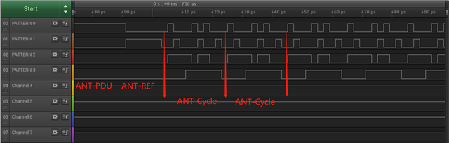
static const uint8_t ant_patterns[] = {0x2, 0x5, 0x1, 0xC,0x09}; // ANT11,ANT1,ANT10,ANT9,ANT4According to the white paper and some other posts, my antenna should switch like this: 11 → 11 → 11 → 11 → 11 → 11 → 11 → 11 → 1→ 10 → 9 → 4→1→ 10 → 9 → 4...
I ran it through the logic analyzer and found it's not true.
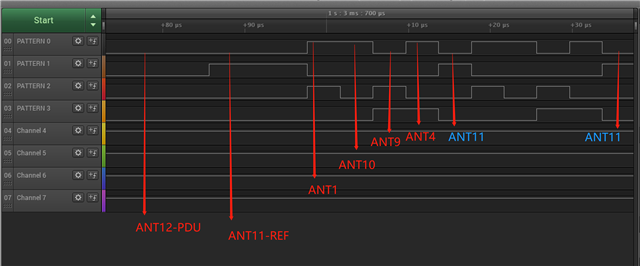
ANT11 of the reference period also participates in the later polling.How exactly do antennas poll? Figuring this out is crucial for the rest of the algorithm