Sequence of Antenna switch pattern

Hi,

I'm testing the NCS direction-finding-connectionless demo, 

NCS V2.6.0

this is my overlay:

&radio {
	status = "okay";
	/* This is a number of antennas that are available on antenna matrix
	 * designed by Nordic. For more information see README.rst.
	 */
	dfe-antenna-num = <12>;
	/* This is a setting that enables antenna 12 (in antenna matrix designed
	 * by Nordic) for Rx PDU. For more information see README.rst.
	 */
	dfe-pdu-antenna = <0x0>;

	/* These are GPIO pin numbers that are provided to
	 * Radio peripheral. The pins will be acquired by Radio to
	 * drive antenna switching when AoA is enabled.
	 * Pin numbers are selected to drive switches on antenna matrix
	 * desinged by Nordic. For more information see README.rst.
	 */
	dfegpio0-gpios = <&gpio0 3 0>;
	dfegpio1-gpios = <&gpio0 4 0>;
	dfegpio2-gpios = <&gpio0 28 0>;
	dfegpio3-gpios = <&gpio0 29 0>;
};

and my ant_patterns:

static const uint8_t ant_patterns[] = {0x2, 0x5, 0x1, 0xC,0x09}; // ANT11,ANT1,ANT10,ANT9,ANT4
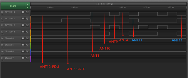
According to the white paper and some other posts, my antenna should switch like this: 11 → 11 → 11 → 11 → 11 → 11 → 11 → 11 → 1→ 10 → 9 → 4→1→ 10 → 9 → 4...
I ran it through the logic analyzer and found it's not true.
ANT11 of the reference period also participates in the later polling.How exactly do antennas poll? Figuring this out is crucial for the rest of the algorithm
Parents
  • by the way, It is correct when using the white paper's proprietary configuration.Here are some of my configurations:

    static uint8_t switch_pattern[] = {0x1,0x2, 0x0, 0x5, 0x6, 0x4,
    					0xC, 0x9, 0xE, 0xD, 0x8, 0xA};
    					
        for(int i=0;i<sizeof(switch_pattern);i++)
        {
            NRF_RADIO->SWITCHPATTERN = switch_pattern[i];
        }

    The reference antenna does not participate in the later cycle

  • Hello again, and thank you for your patience in this case.

    I agree with you on how the switching should work. So this is an unmodified sample you are running, you've just configured the antenna switch pattern?

    If you increase the switch pattern length, ie. add more antennas there, are you seeing the same issue?

    Regards,

    Elfving

Reply Children
  • Hi  Elfving,

    I didn't make any changes except switch pattern. Increasing the switch pattern length has the same result. Thank you for confirming my results.

  • Hello again,

    I think there has been a big misunderstanding here on my part. Sorry about this. Apparently the Product Specification and White Paper we have available on this both show the antenna switching pattern you describe. However, neither of the two describe the way the switching happens in the SDK. They just describe how this is by default done in the HW, and knowing which would make it easier for you if you want to make your own solution for this. The reasoning is that the HW has a lot of capabilities that goes beyond what the SDK provides, and people might want to take advantage of that.

    The samples though, along with the SDK, follows the BLE compliant antenna switching, which is that it goes back to the reference antenna after exhausting the switching array.

    I believe the reason why the default sample doesn't do so is that it maybe doesn't get exhausted during the length of the CTE? Are you not seeing the reference antenna again after the entire list is exhausted?

    Regards,

    Elfving

Related