Issue with IMU Sensor (LSM6DSV16X) Sample Rate in Sensor Hub Mode

I am using an IMU sensor in sensor hub mode (LSM6DSV16X, LIS2MDL) with the FIFO interrupt interval set at 30 Hz. The data is sent over BLE. It works perfectly when using RTT, but when I disable debug mode, the sample rate drops to around 1 Hz.

Could someone please help me resolve this issue?

Thank you.

Parents
  • Thank you for your reply. When the IMU's FIFO is full, an interrupt will occur on the interrupt pin. The interrupt rate will decrease to 1 Hz as if something changes or is missed when I disable the RTT configuration.

  • So what triggers the IMU readings in the first place? Do you have a timer set up at 30Hz or something?

    What HW are you running this on? nRF5340DK? Or do you have a custom board?

  • Hi Naeem,

    Have you had a look at my reply by any chance? Please let me know if you need any further information.

    Bests,

  • Hi Sid,

    Apologies for the delayed response due to high work load.

    I have used the 2 zip files that you uploaded last time (one for the NRF52DK and the other for the 5340DK)

    I am using those projects as it is (without anything changing):

    I can see the output on the console connected to the NRF52DK that is receiving BLE data from the NRF5340DK. I can see that LED and ADC data is printed.

    Next, on the 5340DK, in the main code, I put timestamp when we are setting up the tx_ble_buffer.

    I can see that LED and ADC data is received after 20ms, which matches with what you were saying and expecting.

    Then I connected RTT on 5340DK (using the VS Code Extension-->Connected devices-->5340DK-->RTT)

    I can see that the Interface MCU led is blinking fast, which is showing the RTT connection.

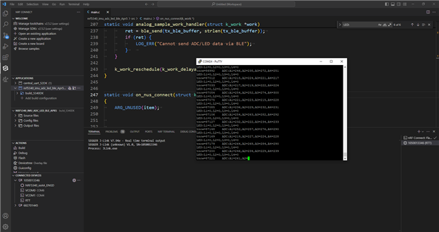
    I can still see on the output that the LED and ADC data is received after 20ms. Snapshot attached where RTT is connected:

  • As I said I did not change anything (except that timestamping in the ble-tx-buffer),

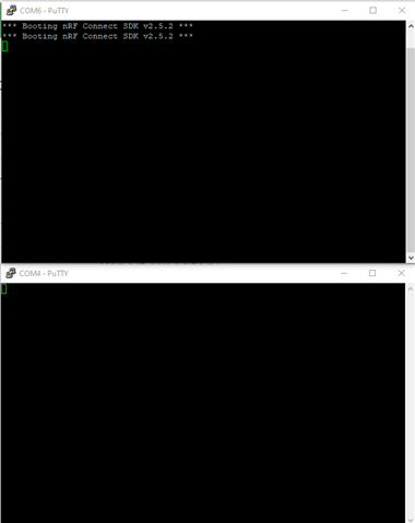
    I am also attaching the console output of 5340DK (which is blank):

  • Hi Naeem,

    Thank you for your consideration.

    Could you please clarify what the "overlay-debug.conf" configuration entails? As I mentioned earlier, in a setup where everything functions correctly, as you indicated, the INT2 of the IMU does not trigger. However, in a setup where the timing and RTT are problematic, INT2 triggers perfectly. I'm trying to understand the relationship between these configurations. 

    In the following configuration, the sensor's part works perfectly, but the timing is correct while RTT is connected:

    # Debug configuration
    
    # Logging
    CONFIG_LOG=y
    CONFIG_LOG_MODE_DEFERRED=n
    CONFIG_LOG_MODE_IMMEDIATE=y
    CONFIG_USE_SEGGER_RTT=y
    CONFIG_CONSOLE=y
    CONFIG_UART_CONSOLE=n
    CONFIG_RTT_CONSOLE=n
    CONFIG_LOG_BACKEND_RTT=n
    CONFIG_LOG_BACKEND_UART=n
    CONFIG_LOG_PRINTK=n
    
    # Troubleshooting
    CONFIG_ASSERT=y
    CONFIG_RESET_ON_FATAL_ERROR=n
    
    
    CONFIG_MAIN_THREAD_PRIORITY=8
    

    Thank you.

  • Hi Sid,

    I have this in the overlay-debug conf:

    # Debug configuration
    
    # Logging
    CONFIG_LOG=y
    CONFIG_LOG_MODE_DEFERRED=n
    CONFIG_LOG_MODE_IMMEDIATE=y
    CONFIG_USE_SEGGER_RTT=y
    CONFIG_CONSOLE=y
    CONFIG_UART_CONSOLE=n
    CONFIG_RTT_CONSOLE=y
    CONFIG_LOG_BACKEND_RTT=y
    CONFIG_LOG_BACKEND_UART=n
    CONFIG_LOG_PRINTK=n
    
    # Troubleshooting
    CONFIG_ASSERT=y
    CONFIG_RESET_ON_FATAL_ERROR=n

    and now I can see what you mean.

    When I connect the RTT, I see logs on the 52DK side coming ~20ms apart

    and without the RTT I see logs on the 52DK side coming ~200ms apart

    I am not sure what is causing this.

    Where have you set the timing parameters that captures samples after fix amount of time? Is it fixed in terms of clock cycles or in terms of time units?

    I also see that ble_send is called in different function, can they (or their callbacks) be somehow dependent upon some other things, like I see that button handler is one that submits imu tap and imu data works.

Reply
  • Hi Sid,

    I have this in the overlay-debug conf:

    # Debug configuration
    
    # Logging
    CONFIG_LOG=y
    CONFIG_LOG_MODE_DEFERRED=n
    CONFIG_LOG_MODE_IMMEDIATE=y
    CONFIG_USE_SEGGER_RTT=y
    CONFIG_CONSOLE=y
    CONFIG_UART_CONSOLE=n
    CONFIG_RTT_CONSOLE=y
    CONFIG_LOG_BACKEND_RTT=y
    CONFIG_LOG_BACKEND_UART=n
    CONFIG_LOG_PRINTK=n
    
    # Troubleshooting
    CONFIG_ASSERT=y
    CONFIG_RESET_ON_FATAL_ERROR=n

    and now I can see what you mean.

    When I connect the RTT, I see logs on the 52DK side coming ~20ms apart

    and without the RTT I see logs on the 52DK side coming ~200ms apart

    I am not sure what is causing this.

    Where have you set the timing parameters that captures samples after fix amount of time? Is it fixed in terms of clock cycles or in terms of time units?

    I also see that ble_send is called in different function, can they (or their callbacks) be somehow dependent upon some other things, like I see that button handler is one that submits imu tap and imu data works.

Children
  • By enabling deferred mode ON by having these configs: 

    CONFIG_LOG_MODE_DEFERRED=y
    CONFIG_LOG_MODE_IMMEDIATE=n

    it turns out that with and without rtt console the timing is same and is ~20ms.

    But as you have mentioned that in this case INT2 does not get fired.

    I have no idea why that could happen. I do not see any conflict in the pins used for interrupt.

    what is use of Signal and Signal_pin?

    I see this in the overlay:

    / {
    	zephyr,user {
    		SIgnal_Pin-gpios = <&gpio1 7 0>;
    	};
    };
    
    / {
    	zephyr,user {
    		SIgnal_Pin-gpios = <&gpio1 7 GPIO_ACTIVE_LOW>;
    	};
    };
    

    it this intentional? (what these pins are used for)?

  • Thank you for your response. I'm so confused as to why INT2 isn't triggered in this configuration. It seems that all settings are identical except for some overlay configurations that might be causing the issue.

    Where have you set the timing parameters that captures samples after fix amount of time? Is it fixed in terms of clock cycles or in terms of time units?

    It's not defined; in fact,  once FIFO is full, IMU will interrupt (INT1).

    what is use of Signal and Signal_pin?

    I used the signal pin for debugging to see if it could toggle on time.

    Best,

  • I am writing whatever related is coming to my mind, so please discard if it is not relevant:

    1) What are differences between int1 and int2. 

    2) How / when these are generated? Are these generated by sensor through some configurations, or automatically?

    3) When would int1 be generated? (approx 20ms? ) and what about int2? 

    4) Could there be conflicts between int1 and int2 timings? Could these both be fired at the same time?

    I see they both are configured in the same was in the overlay, just their pins are different.

    I have also gone through the main.c to see how they are configured, and I see these both are being dealt with in the same way. I do not understand why you are disabling these interrupts in the main() after initializations. This could be just as per your needs though.

    Is this something reproducible in the simulation mode? 

Related