Issue with IMU Sensor (LSM6DSV16X) Sample Rate in Sensor Hub Mode

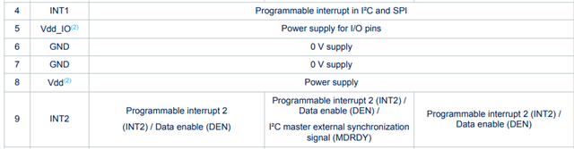
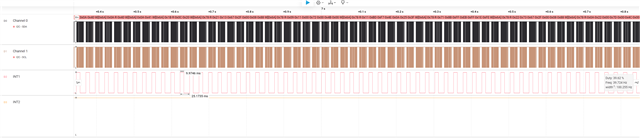
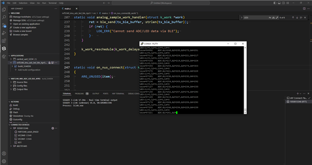
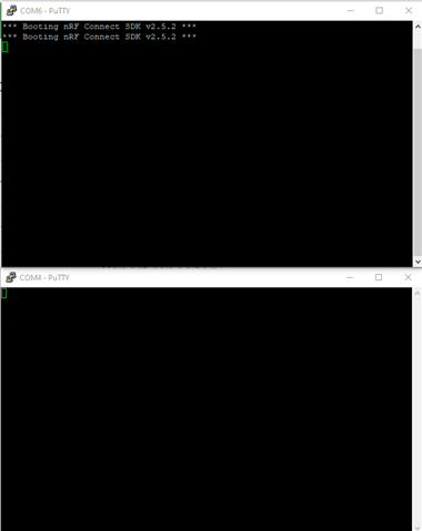
I am using an IMU sensor in sensor hub mode (LSM6DSV16X, LIS2MDL) with the FIFO interrupt interval set at 30 Hz. The data is sent over BLE. It works perfectly when using RTT, but when I disable debug mode, the sample rate drops to around 1 Hz.

Could someone please help me resolve this issue?

Thank you.

Parents
  • Thank you for your reply. When the IMU's FIFO is full, an interrupt will occur on the interrupt pin. The interrupt rate will decrease to 1 Hz as if something changes or is missed when I disable the RTT configuration.

  • So what triggers the IMU readings in the first place? Do you have a timer set up at 30Hz or something?

    What HW are you running this on? nRF5340DK? Or do you have a custom board?

  • Are there any special things with the INT2?

    I see that there are 3 modes in which  sensor could be connected,

    and the role of INT1 is same for all the modes, but INT2 is different.

    I have not used this sensor, but just pointing if that is something to look at.

  • The problem doesn't seem to be with the sensor configuration since I haven't changed anything on the sensor side and get the proper result while the RTT is connected. However, changing the overlay_debug alters the sensor's behavior. I believe there might be an issue with my nRF configuration. What are your thoughts?

    Thsnk you,

  • But this:

    SaeedZadeh said:
    INT1 should trigger approximately every 10 ms, which it does when the RTT is connected. However, when I disconnect RTT, the trigger time significantly increases to around 170 ms.

    does not make sense then, because the RTT is on the DK / MCU side, and the INT1 is generated by sensor which is already configured, right? How changing (logging) behavior can impact the sensor firing interrupt? I do not know about this sensor configurations. 

    Can you print system time when interrupt is generated by the sensor, and then from there we see how much time it is taking between interrupts, so we do not see the logging time but rather interrupt firing time.

    Can you show the changes you made in the overlay?

  • Thank you for your reply. 

    does not make sense then, because the RTT is on the DK / MCU side, and the INT1 is generated by sensor which is already configured, right? How changing (logging) behavior can impact the sensor firing interrupt? I do not know about this sensor configurations. 

    This is why I am confused, as I don't change anything in the main code or IMU, but I change the overlay_debug and have a different result.

    Can you print system time when interrupt is generated by the sensor, and then from there we see how much time it is taking between interrupts, so we do not see the logging time but rather interrupt firing time.

    Please take a look at the image below. You'll notice that INT1 triggers a ~10 ms interrupt, while INT2 remains high, instead of being low and transitioning to high when an event occurs.

    Can you show the changes you made in the overlay?

    I changed the following line to "n" and got the above result. 

    CONFIG_RTT_CONSOLE=y
    CONFIG_LOG_BACKEND_RTT=y

    Best,

    Saeed

  • Hi Naeem,

    Have you had a look at my reply by any chance? Please let me know if you need any further information.

    Bests,

Reply Children
No Data
Related