HI,
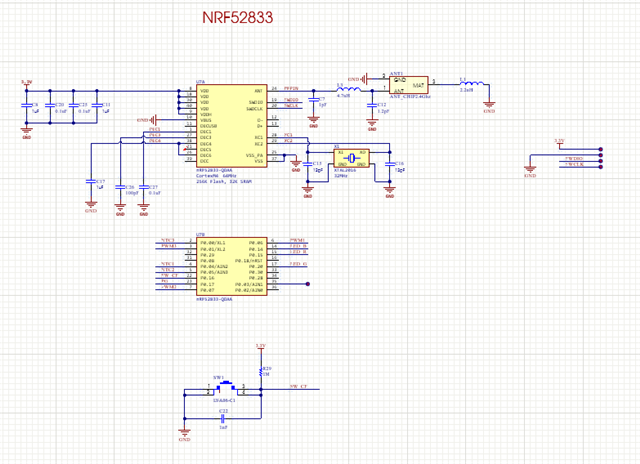
I am building an IoT product using NRF58233 ICs.
In which I use 3 PWM channels and 3 ADC channels.
You can review the principle I attached to make sure nothing went wrong. Thanks
HI,
I am building an IoT product using NRF58233 ICs.
In which I use 3 PWM channels and 3 ADC channels.
You can review the principle I attached to make sure nothing went wrong. Thanks
Hi.
I'll have a look at the schematic and get back to you.
Best regards,
Mathias
thanks
What is your crystal's load capacitance? The capacitors connected to it should have the value Ccap = 2*CL - 4 pF, where CL is the crystal's load capacitance.
Could you please upload your schematic as a vectorised pdf, rather than as a screenshot?
Hi, There are a few things I'm not clear about:
1. Can P0.00/XL1 pin be used as ADC (analog input)
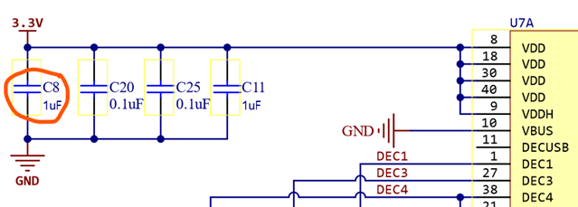
2. Configure the power supplynRF52833.pdf
Hi.
lupinn said:1. Can P0.00/XL1 pin be used as ADC (analog input)
No, the pin used for the positive input to the ADC is chosen in the CH[n].PSELP register and the pin used for the negative input to the ADC is chosen in the CH[n].PSELN register. As you can see there, the inputs named AINx must be used as inputs for the ADC.
Some comments about your schematic follow.


Best regards,
Mathias