Hi
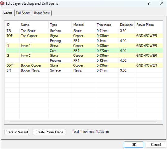
I am designing a 4-layer pcb. How much do you think my signal trace thickness should be?
I use https://www.trgcomponents.de/en/ant-24-cw-rah-rps.html
connector —> www.ozdisan.com/.../954516
Hi
I am designing a 4-layer pcb. How much do you think my signal trace thickness should be?
I use https://www.trgcomponents.de/en/ant-24-cw-rah-rps.html
connector —> www.ozdisan.com/.../954516