Dear Nordic Team,
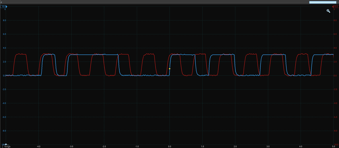
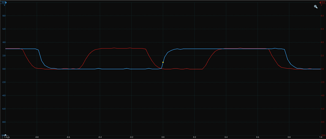
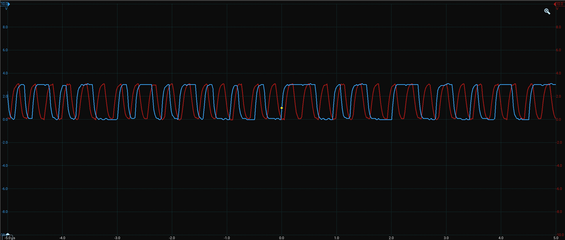
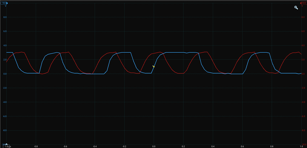
I am currently working with 2 Infineon IM73D122V01 PDM Mems microphones to obtain stereo data, One is configured as left and the other is configured as right channel, To achieve better SNR, Infineon recommends using 3.072MHz PDM Clock, I am currently using 3.2Mhz clock with a ratio of 80.
For testing purposes i have covered the left microphone with glue and playing a fix 500hz tone to the mic and checking the output.
1. For mono recording the setup works I can verify the frequency in STFT graph and i can see that the sensitivity of the left channel is considerable low.
2. For stereo recording i can still verify the frequency on both channels to be correct however the channels have swapped for some reason, left channel is supposed to be less sensitive (low amplitude in time domain plot), however i am getting more sensitivity on left channel as compared to right channel.
3. I have also checked on 1.28MHz PDM clock and Stereo recording is correct (Channels are NOT swapped),
4. I have also checked on different set of Microphones (Vesper VM3000) and i am seeing the same behaviour (Mono channel works correctly for both 1.28MHz and 3.2 MHz, stereo works for 1.28MHz but channel swapped for 3.2MHz).
What could be the reason for the channel swapping at 3.2MHz PDM clock and what is he solution to this problem.
I am using NRF52840 module with NRF5SDK. Any help is greatly appreciated.
Thank you