Wireless Range Issues for nRF24L01+

Hello support.

A new design is looking at using nRF24L01+ to communicate wirelessly. I'm aware that this IC is no longer recommended for new designs, however, it's the one that is currently in the spotlight and being evaluated.

A custom PCB was designed to test the part and exceptional range was verified. To further the investigation, it was then integrated on another custom board with the microntroller used to control it. The layout was altered, but the designer paid more attention to recommdations for this release, so it should have been an improvement. However it was not. Range was greatly diminished. Yet another attempt was made trying to better replicate the example in the datasheet, and range was lacking again.

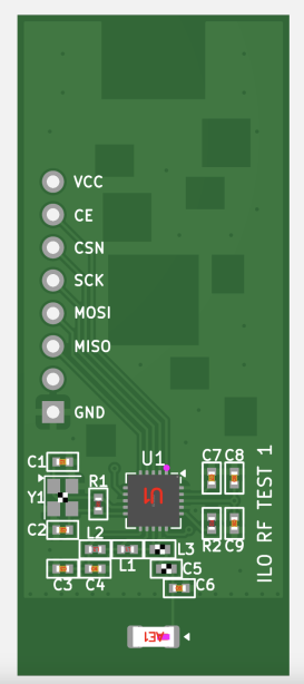
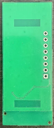
BOM wise, they were all built with same parts. It seems to be the layout that is the deciding factor. I'm wondering if you could look at the layout and see a smoking gun on why V2 and V3 don't work as expected, or why V1 does work properly. I don't have the layout of V1, but I have pictures:

V1 TOP
V1 BOT
V2 TOP/BOT
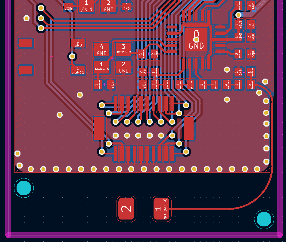
V2 3D
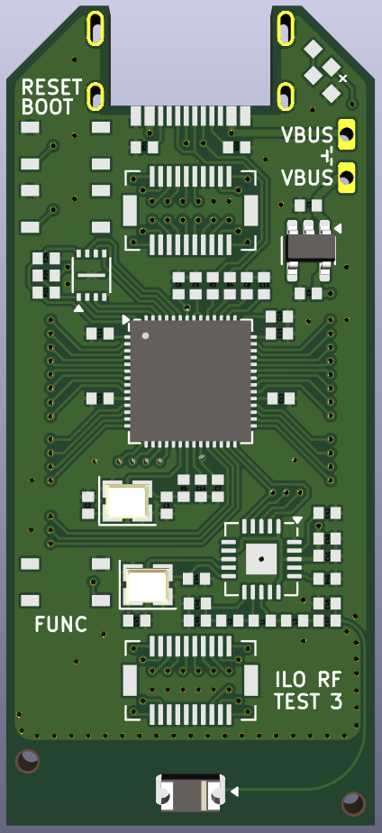
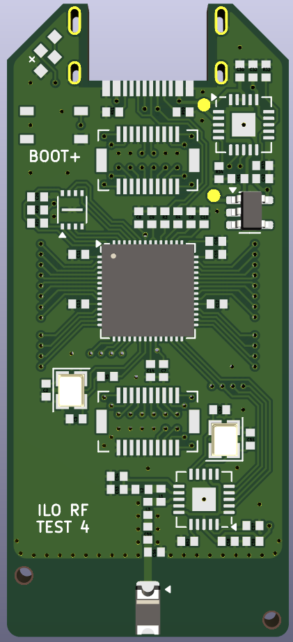
V3 TOP/BOT
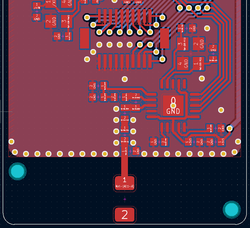
V3 3D
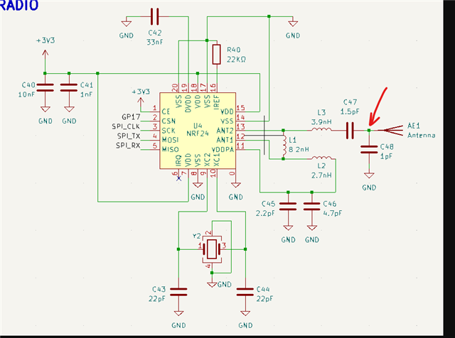
Here's schematic:
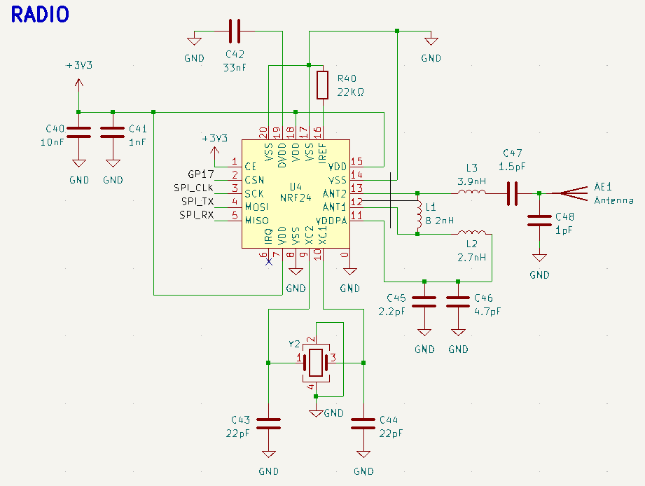
V1 does not have equal length ANT lines, which I know can be problematic, yet it works great. Maybe because of the cutout below the antenna tuning parts.

V2 has a long unmatched trace to the antenna, so I understand why that wouldn't work, but V3 takes care to place and route antenna tuning well. It has a nice solid gnd pour, unlike V2. What am I missing?

Any advice would be appreciated. Thanks!

Parents
  • Hi,

    Can you also share the antenna datasheet? 


    Looks to me that one possible factor is just that the antenna could be de-tuned in the newer designs as location\placement seems different. How is the surrounding changes? Is there any casing or enclosures that would effect the antenna? 


    I dont see a matching network for the antenna so little can be done to tune the antenna if it is de-tuned or whatever reason. 


    Our expert on the nRF24L series is currently out on vacation, but I will do my best to help as best I can in the mean time. 

    Regards,
    Jonathan

  • Hey Jonathan,

    I appreciate your help! Antenna is ANT3216LL00R2400A by Yageo. Currently, testing this in open air on a concept module. Final product will be housed in plastic chassis.

    Another board will be spun, so I'm very open to adding any circuitry that can help tune the antenna. What do you suggest?

    Thanks again for your help!

  • Sorry for a late reply here. 


    stumpja said:
    Another board will be spun, so I'm very open to adding any circuitry that can help tune the antenna. What do you suggest?

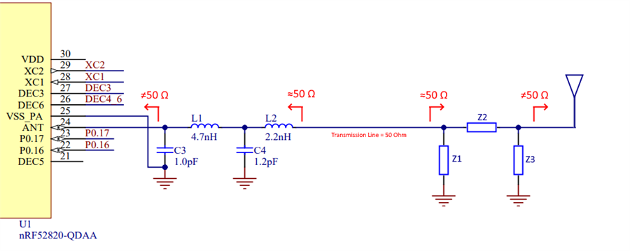
    Best is to always follow the antenna manufacturers recommendation. Bu a Pi- or T- network will do the job in most cases. 


    For just normal inverted F or monopole PCB antennas printed on the circuit board then adjusting the length of the antenna and using a single shunt will do the job. 


    Above is just an example image, dont mind the nRF52 and L and C labeled components.  But this (Z labeled components) is what we usually say for adding matching to antenna's, a simple Pi-network. 

    Regards,
    Jonathan

Reply
  • Sorry for a late reply here. 


    stumpja said:
    Another board will be spun, so I'm very open to adding any circuitry that can help tune the antenna. What do you suggest?

    Best is to always follow the antenna manufacturers recommendation. Bu a Pi- or T- network will do the job in most cases. 


    For just normal inverted F or monopole PCB antennas printed on the circuit board then adjusting the length of the antenna and using a single shunt will do the job. 


    Above is just an example image, dont mind the nRF52 and L and C labeled components.  But this (Z labeled components) is what we usually say for adding matching to antenna's, a simple Pi-network. 

    Regards,
    Jonathan

Children
No Data
Related