Hello,
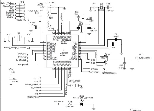
I have a nrf52832-QFAA design that came back from the emissions test lab and they told me that the TX power on the Radio Pin was around -6dBm at the low frequency (2402 MHz). The antenna was milled off and we attached a SMA connector to the output of a impedance matching LPF from Johannson (PN: 2450FM07A0029) to the single ended ANT pin on the nrf52.They are using the nrFConnect DTM program to set TX power to 0dB for testing, channel 37, LE 1Mbps, PRBS9 and 37bytes with no time out. This is my 2nd nrf52832 design and the first one passed at very close to 0dBm. I'm looking at them side by side to see what I did differently and was hoping for a few questions asked.
1) What will cause a drift in measured TX power to default set TX power? Will using the LDO or the internalDCDC affect this?
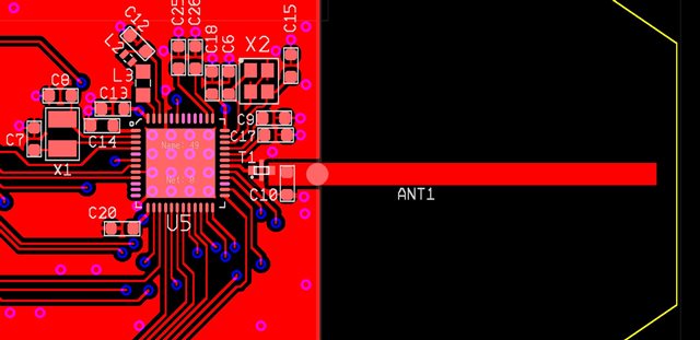
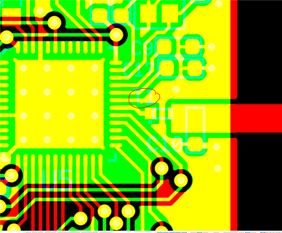
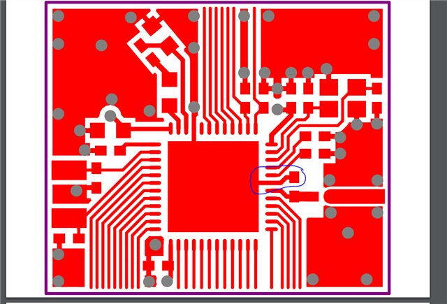
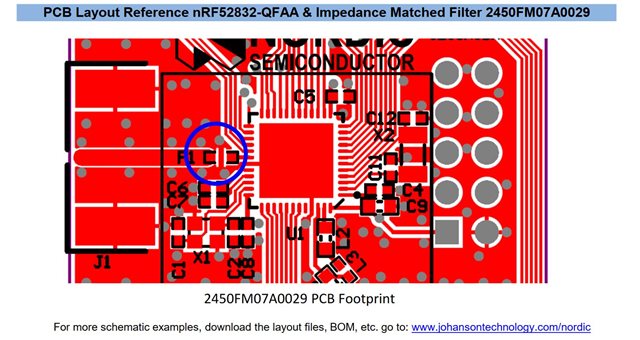
2) So far, the only difference I can remember would be the LPF layout, this design doesn't have two net 0/ground holes on the GND pins of the LPF. The first design I did has it. I don't think that's a big factor, I do have a third design that has that. Will test with that soon. Another thing about this design is I followed the nrf52 Internal DCDC recommended schematic and I had DEC3 with 100pf and left DEC2 a DNS. The first design that passed had both 0.1uF on the two pins, not sure if that will make a difference.
Here's layout and schematic.