
Dear Support Team,
I'm trying to develop a mouse using Pixart's PAW3395 sensor. I've written functions for reading and writing data through the SPI interface. I took help from the bme280 example provided by Zephyr and the Nordic Dev Academy. The overlay remains approximately the same; however, because the power-up sequence of PAW3395 needs us to manually control the "cs" pin thus, I had to assign the cs to 2 nodes: one for the spi (spi1) and the led node (led4). Is there a better way to control the cs pin?
This is the overlay file:
/* STEP 2.1 - Create an overlay file for your board */
&i2c0 {	status = "disabled";};
&spi0 {	status = "disabled";};
&i2c1 {	status = "disabled";};

&spi1 {
    compatible = "nordic,nrf-spim";
    status = "okay";
    pinctrl-0 = <&spi1_default>;
    pinctrl-1 = <&spi1_sleep>;
    pinctrl-names = "default","sleep";
    cs-gpios = <&gpio0 30 GPIO_ACTIVE_LOW>;
    bme280: bme280@0{
        compatible = "bosch,bme280";
        reg = <0>;
        spi-max-frequency = <125000>;
    };
};
/* STEP 2.2 - Change the pin configuration */

&pinctrl {
    spi1_default: spi1_default {
        group1 {
            psels = <NRF_PSEL(SPIM_SCK, 0, 28)>,
                    <NRF_PSEL(SPIM_MOSI, 0, 29)>,
                    <NRF_PSEL(SPIM_MISO, 0, 31)>;
        };
    };
    spi1_sleep: spi1_sleep {
        group1 {
            psels = <NRF_PSEL(SPIM_SCK, 0, 28)>,
                    <NRF_PSEL(SPIM_MOSI, 0, 29)>,
                    <NRF_PSEL(SPIM_MISO, 0, 31)>;
            low-power-enable;
        };
    };
};
/{
    buttons {
        compatible = "gpio-keys";
        button4: button_4 {
            gpios = <&gpio0 27 (GPIO_PULL_UP | GPIO_ACTIVE_LOW)>;
            label = "Push button switch 4";
            zephyr,code = <INPUT_KEY_4>;
        };
    };
    leds {
		compatible = "gpio-leds";
		led4: led_4 {
			gpios = <&gpio0 30 GPIO_ACTIVE_LOW>;
			label = "Green LED 4";
		};
        led5: led_5 {
			gpios = <&gpio0 26 GPIO_ACTIVE_LOW>;
			label = "Green LED 5";
		};
    };

    /* These aliases are provided for compatibility with samples */
    aliases {
        sw4 = &button4;
        led4 = &led4;
        led5 = &led5;
    };
};
And this is how I'm currently doing the power-up sequence:
static const struct gpio_dt_spec led = GPIO_DT_SPEC_GET(DT_ALIAS(led0), gpios);
static const struct gpio_dt_spec motion_pin  = GPIO_DT_SPEC_GET(MOTION_NODE, gpios);
static const struct gpio_dt_spec ncs_pin = GPIO_DT_SPEC_GET(DT_ALIAS(led4), gpios);
static const struct gpio_dt_spec nreset_pin = GPIO_DT_SPEC_GET(DT_ALIAS(led5), gpios);
const struct spi_dt_spec spispec = SPI_DT_SPEC_GET(DT_NODELABEL(bme280), SPIOP, 0);
const struct motion_burst *pMotionBurstData;

static void power_up_sequence(void){
	k_msleep(50);
	//drive NCS pin high and then low
	gpio_pin_set_dt(&ncs_pin,1);
	k_msleep(1);
	gpio_pin_set_dt(&ncs_pin,0);
	paw_write_reg(POWER_UP_RESET_REG, 0x5A);
	k_msleep(5);
	power_up_init_reg();
	uint8_t value;
	for(uint8_t i = 0x02; i<=0x06; i++){
		paw_read_regs(i, value, 1);
	}
}

void cb(const struct device *dev, struct gpio_callback *cb, uint32_t pins){
	//read motion burst
	// update_values_motion_burst();
	gpio_pin_toggle_dt(&led);
}

int main(void)
{
	int err;

	if (!gpio_is_ready_dt(&led) || !gpio_is_ready_dt(&motion_pin) || !gpio_is_ready_dt(&ncs_pin)) {
		return 0;
	}
	err = spi_is_ready_dt(&spispec);
	if (!err) {
		LOG_ERR("Error: SPI device is not ready, err: %d", err);
		return 0;
	}

	gpio_pin_configure_dt(&led, GPIO_OUTPUT_ACTIVE);
	gpio_pin_configure_dt(&ncs_pin, GPIO_OUTPUT_ACTIVE);
	gpio_pin_configure_dt(&nreset_pin, GPIO_OUTPUT_ACTIVE);
	gpio_pin_configure_dt(&motion_pin, GPIO_INPUT);

	gpio_pin_set_dt(&nreset_pin,1);
	k_usleep(10);
	gpio_pin_set_dt(&nreset_pin,0);
	power_up_sequence();			//Power on reset for the sensor

	gpio_pin_interrupt_configure_dt(&motion_pin, GPIO_INT_EDGE_TO_ACTIVE);
	static struct gpio_callback motion_cb_data;
	gpio_init_callback(&motion_cb_data,cb,BIT(motion_pin.pin));
	gpio_add_callback(motion_pin.port, &motion_cb_data);
	uint8_t x[12] = {1,2,3,4,5,6,7,8,9,10,11,12};
	pMotionBurstData = &x;
	while (1) {

		// LOG_INF("%d\n%d\n%d\n%d", pMotionBurstData->Del_X_H, pMotionBurstData->Del_X_L, pMotionBurstData->Del_Y_H, pMotionBurstData->Del_Y_L);
		// update_values_motion_burst();
		uint8_t val=0;
		LOG_INF("Values are:\n");
		paw_read_regs(0x0C,val,1);  //default value 0x01
		LOG_INF("%x\n",val);
		// paw_read_regs(0x02,&val,1);
		// LOG_INF("%x\n",val);
		// paw_read_regs(0x03,&val,1);
		// LOG_INF("%x\n",val);
		// paw_read_regs(0x04,&val,1);
		// LOG_INF("%x\n",val);
		// paw_read_regs(0x05,&val,1);
		// LOG_INF("%x\n",val);
		k_msleep(SLEEP_TIME_MS);
	}
	return 0;
}
This is the power-up Sequence as described in the datasheet:
The power-up initialisation mentioned in point 6 basically involves writing to a bunch of registers on the PAW3395.
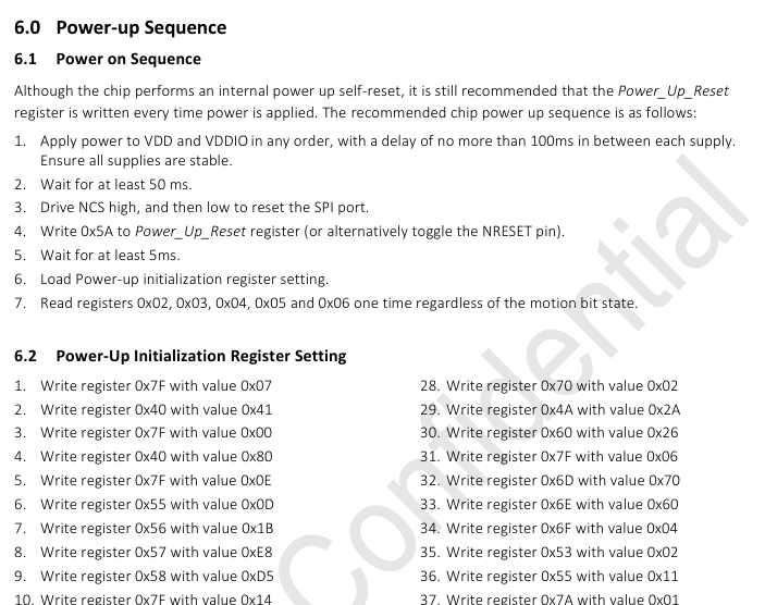
What is the best method to do step 3 in the sequence?
Thank you in advance,
Regards


