Code flashing successful but not working!

Hello,

I am creating a new project that uses the nRF52810 as my controller, and during the development stage, I am using the PCA10040 nRF52832 development board. (I read somewhere that we can flash the nRF52810 code into the nRF52832 PCA10040 development board). My requirement is a simple LED indicator based on delay commands from an APK that uses the Nordic UART service to send and receive data. I added the timer peripheral to the ble_app_uart example project from the directory nRF5_SDK_17.0.2_d674dde\examples\ble_peripheral\ble_app_uart\pca10040e\s112\ses and flashed the code onto the PCA10040 nRF52832 development board to test it. The code works perfectly.

Then I took an nRF52810 custom PCB and connected the JTAG. The board is able to detect and erase the chip. When I flash the code onto the board, the IDE shows "flash successful," but the board is not working. Are there any other conditions for flashing the code into the nRF52810 custom board? Your response is valuable.

SDK version: 17.0.2
SEGGER Embedded Studio version: 5.42a

  • hi ,  , ,I apologize for the previous incorrect response. The debug terminal shows that the code enters this specific case. The issue is actually occurring within the UART event handler. What could be causing this?

    case NRF_DRV_UART_EVT_ERROR:
    NRF_LOG_INFO(" NRF_DRV_UART_EVT_ERROR \n");
    app_uart_event.evt_type = APP_UART_COMMUNICATION_ERROR;
    app_uart_event.data.error_communication = p_event->data.error.error_mask;
    (void)nrf_drv_uart_rx(&app_uart_inst, rx_buffer, 1);
    m_event_handler(&app_uart_event);
    break;

  • Hi,

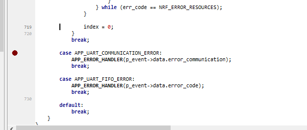
    You can set break point in app_uart_event.evt_type = APP_UART_COMMUNICATION_ERROR;

    And check UART register's ERRORSRC.

    This document shows error root casue.

    https://infocenter.nordicsemi.com/topic/com.nordic.infocenter.nrf52832.ps.v1.1/uart.html?cp=5_2_0_49_9_3#register.ERRORSRC

    typedef struct
    {
        app_uart_evt_type_t evt_type; /**< Type of event. */
        union
        {
            uint32_t error_communication; /**< Field used if evt_type is: APP_UART_COMMUNICATION_ERROR. This field contains the value in the ERRORSRC register for the UART peripheral. The UART_ERRORSRC_x defines from nrf5x_bitfields.h can be used to parse the error code. See also the \nRFXX Series Reference Manual for specification. */
            uint32_t error_code;          /**< Field used if evt_type is: NRF_ERROR_x. Additional status/error code if the error event type is APP_UART_FIFO_ERROR. This error code refer to errors defined in nrf_error.h. */
            uint8_t  value;               /**< Field used if evt_type is: NRF_ERROR_x. Additional status/error code if the error event type is APP_UART_FIFO_ERROR. This error code refer to errors defined in nrf_error.h. */
        } data;
    } app_uart_evt_t;

  • hi ,  , , 

    When I put a breakpoint here and start debugging the code, it never stops at the given breakpoint. The code execution continues until a fatal error occurs.

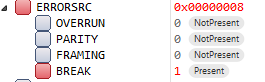
    When I check the ERRORSRC register, I am attaching an image of the ERRORSRC register values.

  • Hi,

    Please refer to spec :

    Break condition

    The serial data input is '0' for longer than the length of a data frame. (The data frame length is 10 bits without parity bit, and 11 bits with parity bit.).

    If you have logic analyzer or oscilloscope, you can measure the waveform of 52810 RX pin.

  • Hi, sorry for the delayed response. solved the issue by changing the UART RX, TX, CTS, and RTS pin numbers. The previously used pin numbers were connected to a motion sensor on the custom PCB via the SPI peripheral. Now the board is able to advertise, send commands, and trigger timer intervals based on the delay command from the APK. I really appreciate your efforts in providing this level of support for our development.

Related