How to set an interrupt on LDSW via GPIO in the NPM1300 using the nRF Connect SDK.

I am using NCS v2.5.1 and working on a project where I need to turn off the system using a button that triggers an interrupt on a GPIO. I want this GPIO to control a load switch to turn it on and off. Where both the GPIO and the load switch are part of the NPM1300. How can I achieve this using the nRF Connect SDK?

Is there any configuration available in overlay file? 

Parents
  • Hi,

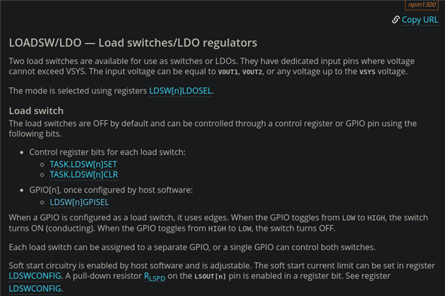
    From Product specification Load switches/LDO regulators:

    "The load switches are OFF by default and can be controlled through a control register or GPIO pin using the following bits."

    Regards,
    Sigurd Hellesvik

  • Hi Sigurd,

    Thank you for the information regarding the control of load switches/LDO regulators through a control register or GPIO pin.

    I was wondering if it’s possible to implement these changes (controlling the load switches) directly via the overlay file in NCS, without modifying the source code. Specifically, I'm looking to set the control through a GPIO pin using the overlay file configuration.

    Any guidance on this would be greatly appreciated.

    Regards,

    Priyesh shahi

  • Hi, yes this is possible.

    You have to add
    enable-gpios = <&npm1300_ek_gpio 0 GPIO_ACTIVE_HIGH>; 
    to the load swtich/LDO settings portion of your overlay.

    You also have to add the gpio controller in the i2c configuration portion of the overlay. 

    example:

    &arduino_i2c {
       npm1300_ek_pmic: pmic@6b {
           compatible = "nordic,npm1300";
           reg = <0x6b>;
    
           npm1300_ek_gpio: gpio-controller {
               compatible = "nordic,npm1300-gpio";
               gpio-controller;
               #gpio-cells = <2>;
               ngpios = <5>;
           };
    
    };
    
    npm1300_ek_ldo1: LDO1 {
        regulator-initial-mode = <NPM1300_LDSW_MODE_LDSW>;
        // soft-start-microamp = <20000>;
        enable-gpios = <&npm1300_ek_gpio 0 GPIO_ACTIVE_HIGH>;
        
    };

  • Hi,

    I tried the approach you suggested by adding enable-gpios = <&npm1300_ek_gpio 0 GPIO_ACTIVE_HIGH>; to the load switch/LDO settings portion of my overlay. I also included the GPIO controller in the I2C configuration section as you advised.

    However, it didn't work as expected. Below is the code I tried:

    &i2c0_default {
    	group1 {
    		bias-pull-up;
    	};
    };
    
    &arduino_i2c {
        npm1300_ek_pmic: pmic@6b {
            compatible = "nordic,npm1300";
            reg = <0x6b>;
     
            npm1300_ek_gpio: gpio-controller {
                compatible = "nordic,npm1300-gpio";
                gpio-controller;
                #gpio-cells = <2>;
                ngpios = <5>;
            };
    
    
    		npm1300_ek_regulators: regulators {
    			compatible = "nordic,npm1300-regulator";
    
                npm1300_ek_ldo1: LDO1 {
    				regulator-init-microvolt = <3300000>;
    				regulator-allowed-modes = <NPM1300_LDSW_MODE_LDSW>;
                    regulator-initial-mode = <NPM1300_LDSW_MODE_LDSW>;
                    // soft-start-microamp = <20000>;
                    enable-gpios = <&npm1300_ek_gpio 3 (GPIO_PULL_UP | GPIO_ACTIVE_LOW)>;             
                };
    		};
             
        };    
     };
    

    Additionally, I found in one of the DT binding files that to make the enable-gpios property work, we might need to set the DVS (Dynamic Voltage Scaling) mode first.

    Could you please advise on the next steps? Should we configure the DVS mode before enabling the GPIO, or is there something else that might be missing?

    Thanks for your help!

  • I see that the nPM1300 One Button sample has not been mentioned in this ticket yet.

    Maybe this sample does what you need?

  • The code snippet I provided earlier is actually from that same sample, but unfortunately, it's not working as expected in my case.

    I want to configure one of the nPM1300 GPIOs to trigger the load switch. 

Reply Children
Related