Hello,
I am trying to do CE, FCC RF test.
I am using nRF52833 and nRF5_SDK_17.0.2_d674dde.
I want DTM to work. DTM is using example source in SDK. What changed in example source is UART communication port.
static void uart_init(void)
{
uint32_t err_code;
const app_uart_comm_params_t comm_params =
{
NRF_GPIO_PIN_MAP(1,00),
NRF_GPIO_PIN_MAP(0,13),
0,
0,
APP_UART_FLOW_CONTROL_DISABLED,
false,
DTM_BITRATE
};
And, control power and LED according to our board characteristics. void it23_board_init(void )
{
nrf_gpio_cfg_output(NRF_GPIO_PIN_MAP(0,8)); // power hold
nrf_gpio_cfg_output(NRF_GPIO_PIN_MAP(1,4)); // power led
nrf_gpio_pin_set(NRF_GPIO_PIN_MAP(0,8)); // power hold set
nrf_gpio_pin_set(NRF_GPIO_PIN_MAP(1,4)); // shock led turn on
}
I've attached main.c.
/**
 * Copyright (c) 2012 - 2020, Nordic Semiconductor ASA
 *
 * All rights reserved.
 *
 * Redistribution and use in source and binary forms, with or without modification,
 * are permitted provided that the following conditions are met:
 *
 * 1. Redistributions of source code must retain the above copyright notice, this
 *    list of conditions and the following disclaimer.
 *
 * 2. Redistributions in binary form, except as embedded into a Nordic
 *    Semiconductor ASA integrated circuit in a product or a software update for
 *    such product, must reproduce the above copyright notice, this list of
 *    conditions and the following disclaimer in the documentation and/or other
 *    materials provided with the distribution.
 *
 * 3. Neither the name of Nordic Semiconductor ASA nor the names of its
 *    contributors may be used to endorse or promote products derived from this
 *    software without specific prior written permission.
 *
 * 4. This software, with or without modification, must only be used with a
 *    Nordic Semiconductor ASA integrated circuit.
 *
 * 5. Any software provided in binary form under this license must not be reverse
 *    engineered, decompiled, modified and/or disassembled.
 *
 * THIS SOFTWARE IS PROVIDED BY NORDIC SEMICONDUCTOR ASA "AS IS" AND ANY EXPRESS
 * OR IMPLIED WARRANTIES, INCLUDING, BUT NOT LIMITED TO, THE IMPLIED WARRANTIES
 * OF MERCHANTABILITY, NONINFRINGEMENT, AND FITNESS FOR A PARTICULAR PURPOSE ARE
 * DISCLAIMED. IN NO EVENT SHALL NORDIC SEMICONDUCTOR ASA OR CONTRIBUTORS BE
 * LIABLE FOR ANY DIRECT, INDIRECT, INCIDENTAL, SPECIAL, EXEMPLARY, OR
 * CONSEQUENTIAL DAMAGES (INCLUDING, BUT NOT LIMITED TO, PROCUREMENT OF SUBSTITUTE
 * GOODS OR SERVICES; LOSS OF USE, DATA, OR PROFITS; OR BUSINESS INTERRUPTION)
 * HOWEVER CAUSED AND ON ANY THEORY OF LIABILITY, WHETHER IN CONTRACT, STRICT
 * LIABILITY, OR TORT (INCLUDING NEGLIGENCE OR OTHERWISE) ARISING IN ANY WAY OUT
 * OF THE USE OF THIS SOFTWARE, EVEN IF ADVISED OF THE POSSIBILITY OF SUCH DAMAGE.
 *
 */
/**
  @defgroup dtm_standalone main.c
  @{
  @ingroup ble_sdk_app_dtm_serial
  @brief Stand-alone DTM application for UART interface.

 */

#include <stdint.h>
#include <stdbool.h>
#include "nrf.h"
#include "ble_dtm.h"
#include "boards.h"
#include "app_uart.h"

#if defined(NRF21540_DRIVER_ENABLE) && (NRF21540_DRIVER_ENABLE == 1)
#include "nrf21540.h"
#endif

// @note: The BLE DTM 2-wire UART standard specifies 8 data bits, 1 stop bit, no flow control.
//        These parameters are not configurable in the BLE standard.

/**@details Maximum iterations needed in the main loop between stop bit 1st byte and start bit 2nd
 * byte. DTM standard allows 5000us delay between stop bit 1st byte and start bit 2nd byte.
 * As the time is only known when a byte is received, then the time between between stop bit 1st
 * byte and stop bit 2nd byte becomes:
 *      5000us + transmission time of 2nd byte.
 *
 * Byte transmission time is (Baud rate of 19200):
 *      10bits * 1/19200 = approx. 520 us/byte (8 data bits + start & stop bit).
 *
 * Loop time on polling UART register for received byte is defined in ble_dtm.c as:
 *   UART_POLL_CYCLE = 260 us
 *
 * The max time between two bytes thus becomes (loop time: 260us / iteration):
 *      (5000us + 520us) / 260us / iteration = 21.2 iterations.
 *
 * This is rounded down to 21.
 *
 * @note If UART bit rate is changed, this value should be recalculated as well.
 */
#define MAX_ITERATIONS_NEEDED_FOR_NEXT_BYTE ((5000 + 2 * UART_POLL_CYCLE) / UART_POLL_CYCLE)

#define MAX_TEST_DATA_BYTES     (15U)                /**< max number of test bytes to be used for tx and rx. */
#define UART_TX_BUF_SIZE 256                         /**< UART TX buffer size. */
#define UART_RX_BUF_SIZE 256                         /**< UART RX buffer size. */

// Error handler for UART
void uart_error_handle(app_uart_evt_t * p_event)
{
    if (p_event->evt_type == APP_UART_COMMUNICATION_ERROR)
    {
        APP_ERROR_HANDLER(p_event->data.error_communication);
    }
    else if (p_event->evt_type == APP_UART_FIFO_ERROR)
    {
        APP_ERROR_HANDLER(p_event->data.error_code);
    }
}

/**@brief Function for UART initialization.
 */
static void uart_init(void)
{
    uint32_t err_code;
    const app_uart_comm_params_t comm_params =
      {
            NRF_GPIO_PIN_MAP(1,00),
            NRF_GPIO_PIN_MAP(0,13),
          0,
          0,
          APP_UART_FLOW_CONTROL_DISABLED,
          false,
          DTM_BITRATE
      };

    APP_UART_FIFO_INIT(&comm_params,
                       UART_RX_BUF_SIZE,
                       UART_TX_BUF_SIZE,
                       uart_error_handle,
                       APP_IRQ_PRIORITY_LOWEST,
                       err_code);

    APP_ERROR_CHECK(err_code);
}

void it23_board_init(void )
{
    nrf_gpio_cfg_output(NRF_GPIO_PIN_MAP(0,8));         // power hold
    nrf_gpio_cfg_output(NRF_GPIO_PIN_MAP(1,4));        // power led

    nrf_gpio_pin_set(NRF_GPIO_PIN_MAP(0,8));           // power hold set
    nrf_gpio_pin_set(NRF_GPIO_PIN_MAP(1,4));           // shock led turn on
}
/**@brief Function for application main entry.
 *
 * @details This function serves as an adaptation layer between a 2-wire UART interface and the
 *          dtmlib. After initialization, DTM commands submitted through the UART are forwarded to
 *          dtmlib and events (i.e. results from the command) is reported back through the UART.
 */
int main(void)
{
    uint32_t    current_time;
    uint32_t    dtm_error_code;
    uint32_t    msb_time          = 0;     // Time when MSB of the DTM command was read. Used to catch stray bytes from "misbehaving" testers.
    bool        is_msb_read       = false; // True when MSB of the DTM command has been read and the application is waiting for LSB.
    uint16_t    dtm_cmd_from_uart = 0;     // Packed command containing command_code:freqency:length:payload in 2:6:6:2 bits.
    uint8_t     rx_byte;                   // Last byte read from UART.
    dtm_event_t result;                    // Result of a DTM operation.

    bsp_board_init(BSP_INIT_LEDS);

    uart_init();

    it23_board_init();

    dtm_error_code = dtm_init();

#if defined(NRF21540_DRIVER_ENABLE) && (NRF21540_DRIVER_ENABLE == 1)
    //Initialization of nRF21540 front-end Bluetooth® range extender chip. Do not use if your hardware doesn't support it.
    APP_ERROR_CHECK(nrf21540_init());
#endif

    if (dtm_error_code != DTM_SUCCESS)
    {
        // If DTM cannot be correctly initialized, then we just return.
        return -1;
    }

    for (;;)
    {
        // Will return every timeout, 625 us.
        current_time = dtm_wait();

        if (app_uart_get(&rx_byte) != NRF_SUCCESS)
        {
            // Nothing read from the UART.
            continue;
        }

        if (!is_msb_read)
        {
            // This is first byte of two-byte command.
            is_msb_read       = true;
            dtm_cmd_from_uart = ((dtm_cmd_t)rx_byte) << 8;
            msb_time          = current_time;

            // Go back and wait for 2nd byte of command word.
            continue;
        }

        // This is the second byte read; combine it with the first and process command
        if (current_time > (msb_time + MAX_ITERATIONS_NEEDED_FOR_NEXT_BYTE))
        {
            // More than ~5mS after msb: Drop old byte, take the new byte as MSB.
            // The variable is_msb_read will remains true.
            // Go back and wait for 2nd byte of the command word.
            dtm_cmd_from_uart = ((dtm_cmd_t)rx_byte) << 8;
            msb_time          = current_time;
            continue;
        }

        // 2-byte UART command received.
        is_msb_read        = false;
        dtm_cmd_from_uart |= (dtm_cmd_t)rx_byte;

        if (dtm_cmd(dtm_cmd_from_uart) != DTM_SUCCESS)
        {
            // Extended error handling may be put here.
            // Default behavior is to return the event on the UART (see below);
            // the event report will reflect any lack of success.
        }

        // Retrieve result of the operation. This implementation will busy-loop
        // for the duration of the byte transmissions on the UART.
        if (dtm_event_get(&result))
        {
            // Report command status on the UART.
            // Transmit MSB of the result.
            while (app_uart_put((result >> 8) & 0xFF));
            // Transmit LSB of the result.
            while (app_uart_put(result & 0xFF));
        }
    }
}

/// @}
I compiled this DTM and uploaded it to the board.
I connected it to the PC and UART (Tx, Rx, Vcc3.3v, GND).
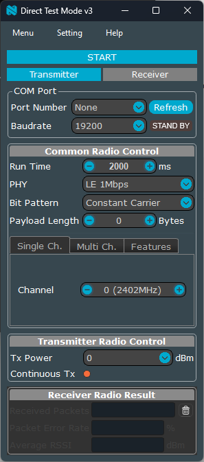
On the PC, I used the nRF-DTM UI-based below.
https://github.com/olleheugene/nRF-DTM/wiki/UI-based-test
I saw the result as shown in the picture below.
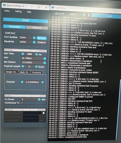
After checking up to this point, I sent the product to the test lab.
However, the test lab saw the output like the picture above, but it is not captured by the actual wireless test equipment.
What is the problem? Is there any way to check if the DTM works without the wireless test equipment?
Thanks