Hello,
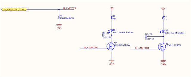
I am currently using an NRF52840 microcontroller (powered at 3.3V) to control two IR LEDs (powered at 5V) via an N-MOSFET. The GPIO pin that controls the N-MOSFET is configured in push-pull mode with a pull-down resistor, as shown in Image 1.
The IR LEDs are intended to be operated in pulsed mode to prevent them from burning out.

Recently, we discovered a firmware bug that caused the GPIO pin to remain continuously active, which resulted in damage to the IR LED drive circuit (N-MOSFET, LEDs, etc.) and the microcontroller itself.
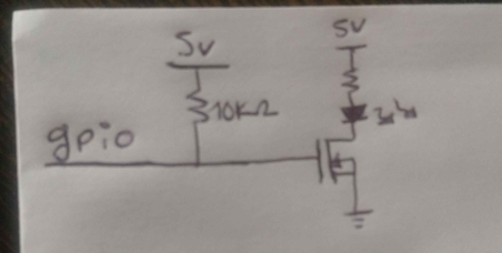
To protect the circuit from potential future bugs of this nature, I am considering reconfiguring the GPIO to open-drain mode, with a pull-up resistor connected to 5V at the N-MOSFET gate to prevent leakage issues. If the pull-up resistor were connected to 3.3V while the IR LEDs are powered at 5V, it could cause leakage current through the N-MOSFET, as shown in Image 2. This change would be implemented while keeping the MCU powered at 3.3V.

Would this approach be effective in protecting the circuit? Could connecting the pull-up resistor to 5V while the MCU is powered at 3.3V cause any problems?
Thanks for your help


