Driving a IR LED at 5v while MCU is powered at 3.3V

Hello,

I am currently using an NRF52840 microcontroller (powered at 3.3V) to control two IR LEDs (powered at 5V) via an N-MOSFET. The GPIO pin that controls the N-MOSFET is configured in push-pull mode with a pull-down resistor, as shown in Image 1.

The IR LEDs are intended to be operated in pulsed mode to prevent them from burning out.
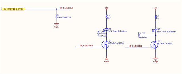
Recently, we discovered a firmware bug that caused the GPIO pin to remain continuously active, which resulted in damage to the IR LED drive circuit (N-MOSFET, LEDs, etc.) and the microcontroller itself.

To protect the circuit from potential future bugs of this nature, I am considering reconfiguring the GPIO to open-drain mode, with a pull-up resistor connected to 5V at the N-MOSFET gate to prevent leakage issues. If the pull-up resistor were connected to 3.3V while the IR LEDs are powered at 5V, it could cause leakage current through the N-MOSFET, as shown in Image 2. This change would be implemented while keeping the MCU powered at 3.3V.
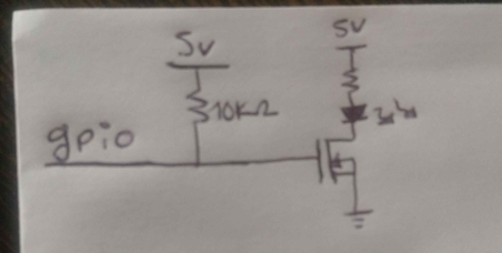
Would this approach be effective in protecting the circuit? Could connecting the pull-up resistor to 5V while the MCU is powered at 3.3V cause any problems? 

Thanks for your help

  • Perfect! Two BAT54 or one BAT54A with a common Gnd.

    As an aside, where is the 5V coming from? If this is (say) a USB device, then that makes sense but if instead the 5V is generated by something like a boost regulator from a lower voltage there are other options for driving something like an IR LED (or motor, or solenoid, etc). Instead of having a 15uSec high-current burst often it is better to charge a capacitor bank over a longer period and discharge that bank through the IR LED. The advantage of a relatively slow charge allows something like a CR2032 coin cell to use IR LEDs without shortening the coin battery life. Stored charge is CV, so control charge voltage V via a PWM voltage inverter (a trivial circuit) and use the same circuit you have now to discharge the capacitor through the IR LED. If this is an optical project typically the illumination pulse relies on the energy emitted and not the specific envelope of the emission.

    Detecting mastitis in cow's milk takes two IR LEDs and two photodiodes and the ratiometric value indicates imbalance in flow discolouration across a dark mesh. Hot steel rod vibrating at high speed can be frozen in time on a linear CCD or photodiode array to give precise measurements of diameter. Phased pulsing of two IR LEDs within a single frame capture on a global shutter area camera can freeze the flight of a golf ball or other moving object allowing determination of rotation, speed and angle of travel and thus prediction of flight path. Short discharge pulses onto the IR LED matched with narrow-band optical filters make measurements less affected by sunlight or factory argon lights. Of course some IR LEDs allow higher pulse discharge voltages than others, which affects component choice. I once used 100V for 200nSec pulses, equivalent to 4uSec at 5V.

    Using PPI and PWM to create a voltage doubler or tripler on the nRF52:

    // Voltage Doubler
    //
    //        |\  (         |\  (          |Measure V
    // Phase 0| \ )         | \ )          |
    //   -----|  )----#-----|  )-----#-----#------+
    //        | / (   |     | / (    |            |
    //        |/  )   |     |/  )    |           --- LED
    //                |              |           \ / =>
    //              -----            |           ---
    //              -----          -----          |
    //                |            -----        |-+
    //                |              |      +-->|
    //                |              |      |   |-+
    //                |              |      |     |
    //                |            =====    |   =====
    //                |             ===     |    ===
    //            Phase 1            =    Disch   =
    
    // Voltage Tripler
    //
    //        |\  (         |\  (         |\  (          |Measure V
    // Phase 0| \ )         | \ )         | \ )          |
    //   -----|  )----#-----|  )----#-----|  )-----#-----#------+
    //        | / (   |     | / (   |     | / (    |            |
    //        |/  )   |     |/  )   |     |/  )    |           --- LED
    //                |             |              |           \ / =>
    //              -----         -----            |           ---
    //              -----         -----          -----          |
    //                |             |            -----        |-+
    //                |             |              |      +-->|
    //                |             |              |      |   |-+
    //                |             |              |      |     |
    //                |             |            =====    |   =====
    //                |             |             ===     |    ===
    //            Phase 1        Phase 2           =    Disch   =
    

    nrf52840-1-8v-driving-rgb-led

  • Thanks again for your patient and your explanations !

    For the moment, the IR LEDs are powered with an usb charger, so if I understand well, the first circuit that you recommended is OK. 

    Once our design will be validated by some consumers we will update it to a battery powered circuit so, this information will help me a lot ! 

Related