Driving a IR LED at 5v while MCU is powered at 3.3V

Hello,

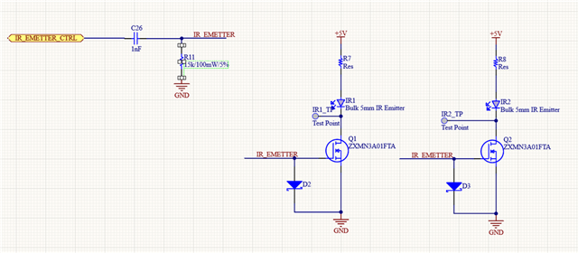
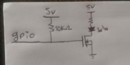
I am currently using an NRF52840 microcontroller (powered at 3.3V) to control two IR LEDs (powered at 5V) via an N-MOSFET. The GPIO pin that controls the N-MOSFET is configured in push-pull mode with a pull-down resistor, as shown in Image 1.

The IR LEDs are intended to be operated in pulsed mode to prevent them from burning out.

Recently, we discovered a firmware bug that caused the GPIO pin to remain continuously active, which resulted in damage to the IR LED drive circuit (N-MOSFET, LEDs, etc.) and the microcontroller itself.

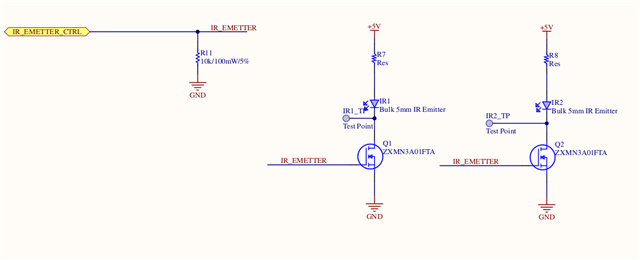
To protect the circuit from potential future bugs of this nature, I am considering reconfiguring the GPIO to open-drain mode, with a pull-up resistor connected to 5V at the N-MOSFET gate to prevent leakage issues. If the pull-up resistor were connected to 3.3V while the IR LEDs are powered at 5V, it could cause leakage current through the N-MOSFET, as shown in Image 2. This change would be implemented while keeping the MCU powered at 3.3V.

Would this approach be effective in protecting the circuit? Could connecting the pull-up resistor to 5V while the MCU is powered at 3.3V cause any problems? 

Thanks for your help

  • The pull-up is a bad idea and will result in the IR LED being on any time the nRF52 is in reset or not correctly running firmware. This issue is as old as the hills, if I may say so. The trick is to not allow any fixed GPIO pin state to keep the FET (and LED) on; the simplest solution is to keep your original circuit but insert a 1nF capacitor at the GPIO port pin driving both the FET Gate and the pull-down resistor on the FET Gate. To turn the FET on use a pulse (or series of pulses) on the GPIO pin; a fixed high or low on the IO pin will eventually result in the FET turning off as the 3.3V on the capacitor decays. The CR time-constant controls how long the FET (and LED) stays on for each low-to-high edge on the GPIO pin. Make this time longer than required for a single pulse, such that the actual LED on time is the width of the active-high GPIO pin pulse; the decaying voltage on the capacitor (which will eventually turn off the LED) is only used in case the GPIO pin "forgets" to go low. Increase the pull-down resistor value to lengthen the "on" time of the IR LED; try to avoid large coupling capacitor values to avoid stressing the GPIO pin..

    Choose a FET with a Gate schottky clamp diode between Gate and Gnd to stop negative voltages appearing on the Gate when the GPIO pin changes from high-to-low, Some FETs have an internal pull-down to Gnd in addition to the schottky clamp diode, but the external pull-down resistor is fine; do not rely solely on the internal nRF52 internal pull-down as the internal pull-down is not active some of the time (power-on reset, software bug, ..).

    For safety-critical applications, typically driving a solenoid or laser diode, a secondary fail-safe would be mandatory, typically a clamp FET or series FET such that both FETs on separate drivers have to be in the correct state to energise.

    A FET something like the NMOS ntnd31225cz would work; you could lso just the the FET you already have as the Vgs spec allows negative voltages but that would probably adversely affect the timing between adjacent pulses.

    Edit: On reflection maybe just keep the FETs you are already using and add external schottky from the Gate to Gnd for each FET.

  • Hello !


    Thank you so much for your response! I just want to make sure I understood it correctly. Could you please take a look at my new design?

    The LED's single pulse duration is 13 µs, so I extended this time to 20 µs. Based on the formula T = CR, I calculated the resistance as R = 20 kΩ. Does this seem correct to you?

    Thanks again for all your help!

    Best regards,

    Estibaly

    EDIT: in the schematics the Resistance is 15kΩ but I modified it to 20k.

  • Yes that looks good, except the schottky diodes D2 and D3 look like they are drawn upside-down; these diodes are required to clamp any negative going voltages to Gnd (not positive voltages). The key to the values lie in the gate threshold voltage of the FET, which as usual has a hopelessly loose specification of between 1 and 2 volts depending on temperature, pressure and day of week. AC Coupled FET ZXMN3A01FTA drive to IR LED, let's assume the FET (parameter Vgsth) turns off at (say) 2V to be sure the drive is always sufficient:

    AC Coupled FET ZXMN3A01FTA drive to IR LED, assume Vgsth turns off at (say) 2V:
    Key:
        Vs Starting pulse voltage measured on C26 (=Vdd, volts)      3.1 volts
        Vd Decaying measured voltage measured on C26 (=Vgsth. volts) 2.0 volts
        C  Primary storage capacitor C26 1nF
        t  Measurement (decay) interval Vs to Vd (seconds)           20 uSecs
        R  Resistance to drain C26 from Vs to Vd (Ohms)
        Vd = VsE^(-t/CR)
        ln(Vd/Vs) = -t/CR
        R = -t/(C*ln(Vd/Vs)
        R11 = (-20us)/(1nF * ln(2/3.1) = 45k
        So use 1nF and 45K
    Set high-drive on the GPIO port to ensure clean waveforms.

    So use 1nF and 45K and set high-drive on the GPIO port to ensure clean waveforms presented to the capacitor and FET gate. Remember the capacitor decay is the safe turn-off of the FET in case the GPIO misbehaves; normally it will be the clean sharp edges from GPIO which turns the FET and IR LED on and off.

  • Not sure if you see edits so repeating my edit above:

    Schottky diodes D2 and D3 look like they are drawn backwards; these diodes are required to clamp any negative going voltages to Gnd (not positive voltages).

  • Hello,

    Thanks a lot for your great explanations ! I have another question about Schottky diodes, is there any specifications that I must consider ? I choose BAT54-HE3-08 https://www.vishay.com/docs/86410/bat54_bat54a_bat54c_bat54s.pdf

    Does it seems correct for you ?

    Have a nice day

Related