This post is older than 2 years and might not be relevant anymore
More Info: Consider searching for newer posts

Why the inrush current at startup is about 500mA

When I use a power supply, (3.0Volts-60mA limitation) with the DevKit boards nRF51 or nRF52 the input voltage is clamped at around 2.0 V and the current is 60mA : the SoC doesn’t start.

By increasing the current limitation, step by step, the SoC start, with the current threshold of 80mA.

After the start up, the current of the devKit is low as expected. (With the software ble_peripheral>ble_app_hts s110 for nRF51 or s132 for nRF52).

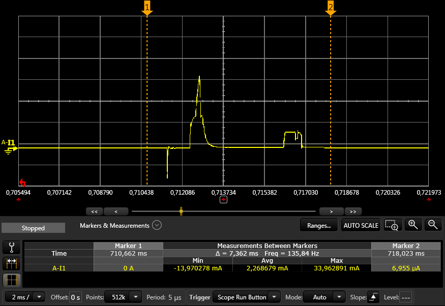
I've checked the inrush current with a scope. I've seen a pulse of 500mA and 30µs width .

  • Hi Frederic

    There are two chips on the nRF51-DK board. One is nRF5x, the other is Segger chip. Nordic does not provide specification for the Segger chip. To measure the current on the nRF51 chip, you should follow section 5.7 in the nRF51-DK user guide. These methods you can use for measuring current for the nRF51 chip on the nRF51-DK board. Information on measuring current for the nRF52 kit is given on the following links (1) (2) (3)

    The startup current consumption however for the nRF5x is not specified, i.e. until the chip comes out of reset state. When nRF5 comes out of reset state, the current consumption is specified.

  • Hi Stefan,

    Indeed on these DK boards there is the Segger but I didn't measure it, just the nRF5x. I've also my own boards without the Segger and I have the same peak of current at startup. The current consumption after the nRF5x comes out of reset state is as specified in the datasheet.

    During the VCC rising I have to know the worst case because I have an external power supply with a limited current. The inrush current I've measured (500mA during 30µs) is not acceptable for most of our applications. Please could you make the same measure at startup to be able to specify this current.

    Best regards Frederic.

  • I measured the startup_current on a nRF52QFAABB chip. See the below image.

    The measurement was done using an Agilent N6705B power analyzer, with a sampling interval of 5us. The power analyzer is used as a power supply and has close to zero internal resistance. I get a maximum peak of 34 mA.

    What are you using as power supply? And which chip revision do you have?

    The nRF52 internal power supply charges up caps, and if your power supply has zero internal resistance you might get a high peak, because nothing is limiting the inrush current when the chip starts up. But from what I know zero internal resistance is not a realistic scenario except when you are using high performance lab equipment.

    You say that you can see 500 mA over a period of 30us. That is some narrow spike. I think that adding a series resistance of a couple of Ohm at the input would even out this.

    image description

    EDIT

    So, the startup current in the above plot is the decoupling caps drawing current.

    The development kit has a decoupling cap at 4.7uF at VDD_nRF. And with close to zero internal resistance of the power supply (which is the case with high performance lab equipment, and some batteries), nothing is holding back the inrush current when the caps are charging up.

    New measurements I did with the development kit (using a 4.7uF decoupling cap) was showing an inrush current of 453mA over 30us. This gives a total charge of 13.6uC. 13.6uC over 3V corresponds to a capacitance of 4.5uF, which is not too far off.

    You can try to remove the 4.7uF cap (C9). However, there are still more decoupling caps (100nF) at VDD_nRF and DEC1, so you will probably still see a spike, but it will be much lower. Adding a series resistance at the input would reduce the current spike even more.

Related