Using radio_test sample on custom board.

Hi,

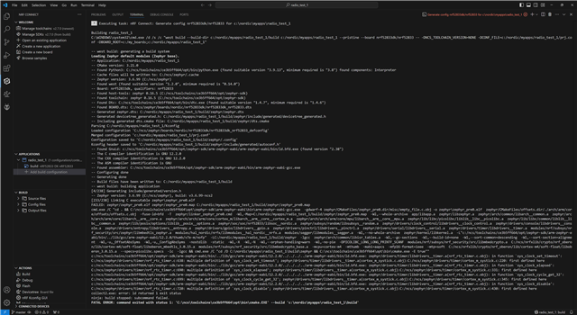
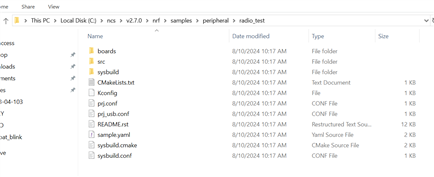
I want to run the radio_test sample on a custom board, how do I go about doing this?

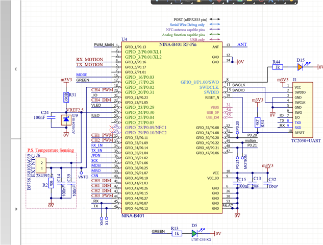
The custom board uses a UBLOX NINA B401- which utilises the nRF52833 chip. Do you have any examples available for the UBLOX NINA B401 chip, including how to set up a dts for custom boards etc. 

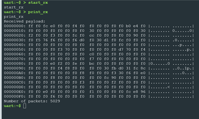
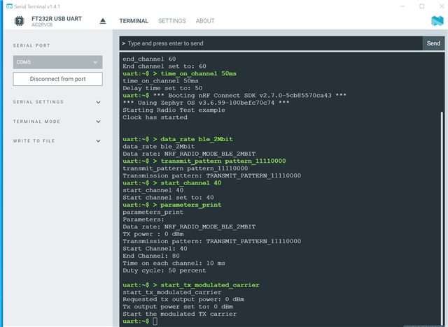
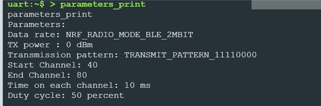
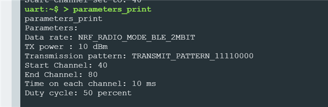
I have the radio test sample running successfully using two nRF52840-DK boards, using nRF connect SDK on Visual Studio.

Parents Reply
  • I fixed this issue by including CONFIG_CORTEX_M_SYSTICK=n in proj.conf. And successfully got the radio test running on nrf52833 DK, however now when attempting on my custom board using Ublox NINA B401. I am not getting any response. 

    Rather than adding overlay file, I edited the .dtsi file to match my board making it 

    &pinctrl {
        uart0_default: uart0_default {
            group1 {
                psels = <NRF_PSEL(UART_TX, 0, 17)>;
                    //<NRF_PSEL(UART_RTS, 0, 5>;
            };
            group2 {
                psels = <NRF_PSEL(UART_RX, 0, 16)>;
                    //<NRF_PSEL(UART_CTS, 0, 7)>;
                bias-pull-up;
            };
        };
    Note I have commented out the RTS and CTS code as I do not have these connections on my board will that be an issue?
    My proj.conf is:
    CONFIG_CONSOLE_HANDLER=y
    CONFIG_SHELL=y

    CONFIG_DYNAMIC_INTERRUPTS=y

    CONFIG_NRFX_TIMER0=y

    CONFIG_ENTROPY_GENERATOR=y
    CONFIG_NRF_SECURITY=y

    CONFIG_FEM_AL_LIB=y
    CONFIG_CORTEX_M_SYSTICK=n
    CONFIG_BOARD_ENABLE_DCDC=n
     
    los is it possible to use the nrf connect serial terminal for chips connected via JTAG, as currently my board is not coming up in the available devices. Therefore I am using a python script currently to read the serial data, which I am not recieing any and I am expecting: 
    Clock has started
Children
  • Hi,

    nicoled123 said:
    I fixed this issue by including CONFIG_CORTEX_M_SYSTICK=n in proj.conf.

    I see. It should not be needed though, and the sample builds out of the box for the nRF52833 DK on my end. Could it be that you have (inadvertedly or not) made some changes to the SDK? It could be worth wonloading the SDK and toolchain again to know that you have a good starting point.

    nicoled123 said:
    Note I have commented out the RTS and CTS code as I do not have these connections on my board will that be an issue?

    There is no need to comment out the flow control pin configuration. The default configuration for the DK does not enable flow control as the hw-flow-control property is not present. You can verify this by looking at the generatd zephyr.dts file in the build folder. And if you have a board where it is defined you can remove it in the board file or add an overlay with the following (adjust to another uart instance if not using uart0):

    &uart0 {
         /delete-property/ hw-flow-control;
    };

    nicoled123 said:
    los is it possible to use the nrf connect serial terminal for chips connected via JTAG, as currently my board is not coming up in the available devices.

    You can use PuTTY or another serial terminal of your choise as well.

    Note that if you still have problems you can use Segger RTT with the radio test example, by adding the following to prj.conf if you have a Segger debugger:

    CONFIG_USE_SEGGER_RTT=y
    CONFIG_SHELL_BACKEND_RTT=y

    But please be aware that RTT does continious access to the device which will cause noise and affect the measurements, so you should keep that in mind. 

    Br,

    Einar

  • Thanks for your help!  I reinstalled SDK and toolchains and that fixed the need for adding   CONFIG_CORTEX_M_SYSTICK=n in proj.conf.

    However I am still having issues running samples on my custom board. I am currently to run the simple blinky sample and no luck. I have tried adding an overlay to nrf52833 DK to change led0 from 13 to 28 and no luck! I have also tried creating a custom board. I have attached the custom board folder and also the blinky project I am working with (I have tested on nrf52833DK and it works on it). Also please see image below for pin out of my custom board. 

    I have tried flashing the board via nrf Connect VS code, programmer from nrf Connect Desktop and also JFlash.  I am using a Jlink Segger Plus to flash the board.  wombat_nina.zip1526.BLINKY.zip

  • Hi,

    Good to hear you were able to rever back to a clean SDK.

    Regarding the Blinky sample not working, the attached proejct fonfiguration does not include clock onfiguration, so the default configuration for the board is used. I see in your build folder that you have not made the change elsewhere either, as CONFIG_CLOCK_CONTROL_NRF_K32SRC_XTAL=y is used. And this will not work on your board.

    You need to add CONFIG_CLOCK_CONTROL_NRF_K32SRC_RC=y to prj.conf in order for this to work.

  • Hi,

    That fixed the issue! I know can run blinky and the radio sample on the custom board.

    In radio sample I am using a 52840 DK with my custom board and the RX payload did not match the transmission pattern.  Is this a result of having a FEM connected but not supporting it in the software yet? 

    My board has a nrf21540 FEM connected, so I am now trying to add support for it. I am trying to follow to seps to add the dts-nrf21540-fem.overlay to the project however it says it is located in samples/peripheral/radio_test folder, however I cannot find it. See below:

    It is also not within any of the subdirectories in this folder. Do you have a copy of this file? And to confirm to include support for this FEM I simply add the overlay, change the GPIO pins to match my board? Or what else must be added to the proj.conf for this?

    ^this approach is described in Radio test — nRF Connect SDK 1.5.1 documentation (nordicsemi.com)

    Another document : Radio front-end module (FEM) support — nRF Connect SDK 1.5.1 documentation (nordicsemi.com) says to add 

    It  says 

    'Before you add the devicetree node in your application, complete the following steps:

    1. Add support for the MPSL library in your application. The MPSL library provides API to configure FEM. See Integration notes in the nrfxlib documentation for details.

    2. Enable support for MPSL implementation in nRF Connect SDK by setting the CONFIG_MPSL Kconfig option to y. '

    Could you clarify the process of adding support for MPSL in application?

    Thanks for your help!

  • I added the FEM node described in  Radio front-end module (FEM) support — nRF Connect SDK 1.5.1 documentation (nordicsemi.com)  and it built with no errors and successfully flashed, now when i check parameters on both kits i get different TX power:

    52840 DK:

    custom board:


    When i go to change the TX power on 52840 to match 10dBm on custom board using command output_power it is not possible to achieve the 10dBm which my custom board reads

    Is it ok for the 52840 DK to not have the same TX power as custom board in this test, I understand the additional power for custom board comes from FEM gain. or do i need to use two boards with FEM?

    Additionally, when I go to Set nRF21540 Front-End-Module parameters. I get options:

    I want to adjust power and tried setting 

    CONFIG_RADIO_TEST_POWER_CONTROL_AUTOMATIC=n in proj.conf but i get error CONFIG_RADIO_TEST_POWER_CONTROL_AUTOMATIC was already disabled. Missing dependencies: FEM but when added FEM i get error CONFIG_FEM was assigned the value y, but got the value n. Missing dependencies: MPSL_FEM_ANY_SUPPORT. I keep adding the dependencies but another is thrown am I missing something? 

    Could you explain the rx and tx sweep functions too and what to be expected to see. Also is it possible to connect the custom board to the RSSI viewer to get a visual representation of the sweep, as currently it says 'no device set up found'

Related