
Hello everyone,
I have a custom board with a nRF5340 on it that is used as a BLE reader for mobile phones. Now we wanted to do some EMC testing. For this we need to broadcast at max power on a single BLE channel at a time. Well, sounds like a job for the direct_test_mode (DTM) sample. I am using SDK v2.2.0 for this, as the BLE code itself is currently based on the central_bas project from this SDK version.
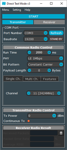
A nRF52840DK is used as a sniffer in combination with the nRF Connect RSSI Viewer. This one is working perfectly fine. For initial testing I took a nRF5340DK as a DTM device, built the DTM sample without changing anything and flashed it. To control the nRF5340 with the DTM firmware I am using the Direct Test Mode v3 utility from Github. This is because on the custom board I need to communicate via UART with the nRF. Using the nRF-DTM-3.1.1 release and the following configuration produced the desired results. The nRF5340 began broadcasting on the 2424 MHz channel and the nRF52840 picked it up. So far so good.
Now I needed to get it working on my custom board. I knew from the central_bas code that usually runs on the nRF5340 that the devicetree file needed adjustments as well as some new lines in the prj.conf. The devicetree file and the prj.conf used in the central_bas project look like this:
nrf5340dk_nrf5340_cpuapp.overlay
// To get started, press Ctrl+Space to bring up the completion menu and view the available nodes.

// You can also use the buttons in the sidebar to perform actions on nodes.
// Actions currently available include:

// * Enabling / disabling the node
// * Adding the bus to a bus
// * Removing the node
// * Connecting ADC channels

// For more help, browse the DeviceTree documentation at https://docs.zephyrproject.org/latest/guides/dts/index.html
// You can also visit the nRF DeviceTree extension documentation at https://nrfconnect.github.io/vscode-nrf-connect/devicetree/nrfdevicetree.html
// This information was auto-generated when this file was created in VS Code

/ {
	chosen {
		nordic,nus-uart = &uart1;
	};
};

&uart0 {
	status = "okay";
	current-speed = <115200>;
	pinctrl-0 = <&uart0_default_overlay>;
	pinctrl-1 = <&uart0_sleep_overlay>;
	pinctrl-names = "default", "sleep";
};

&uart1 {
	status = "okay";
	current-speed = <115200>;
	pinctrl-0 = <&uart1_default_overlay>;
	pinctrl-1 = <&uart1_sleep_overlay>;
	pinctrl-names = "default", "sleep";
};

// TODO: add missing pin configuration
// sda-pin = < 0x16 >;
// scl-pin = < 0x17 >;
&i2c1 {
	status = "disabled";
};

// TODO: add missing pin configuration
// io-pins = < 0xf >;
&qspi {
	status = "disabled";
};

&pinctrl {
	uart0_default_overlay: uart0_default_overlay {
		group1 {
			psels = <NRF_PSEL(UART_TX, 0, 28)>,
				<NRF_PSEL(UART_RTS, 0, 30)>;
		};
		group2 {
			psels = <NRF_PSEL(UART_RX, 0, 26)>,
				<NRF_PSEL(UART_CTS, 0, 31)>;
			bias-pull-up;
		};
	};

	uart0_sleep_overlay: uart0_sleep_overlay {
		group1 {
			psels = <NRF_PSEL(UART_TX, 0, 28)>,
				<NRF_PSEL(UART_RX, 0, 26)>,
				<NRF_PSEL(UART_RTS, 0, 30)>,
				<NRF_PSEL(UART_CTS, 0, 31)>;
			low-power-enable;
		};
	};

	uart1_default_overlay: uart1_default_overlay {
		group1 {
			psels = <NRF_PSEL(UART_TX, 1, 2)>;
		};
		group2 {
			psels = <NRF_PSEL(UART_RX, 0, 13)>;
			bias-pull-up;
		};
	};

	uart1_sleep_overlay: uart1_sleep_overlay {
		group1 {
			psels = <NRF_PSEL(UART_TX, 1, 2)>,
				<NRF_PSEL(UART_RX, 0, 13)>;
			low-power-enable;
		};
	};
};

&{/} {
	leds {
		compatible = "gpio-leds";
        led0: led_0 {
			gpios = < &gpio0 0x13 0x1 >;
			label = "Green LED 0";
		};
        led1: led_1 {
			gpios = < &gpio0 0x15 0x1 >;
			label = "Green LED 1";
		};
        led2: led_2 {
			gpios = < &gpio1 0x08 0x1 >;
			label = "Green LED 2";
		};
        led3: led_3 {
			gpios = < &gpio1 0x06 0x1 >;
			label = "Green LED 3";
		};
        led4: led_4 {
			gpios = < &gpio1 0x04 0x1 >;
			label = "Green LED 4";
		};
	};

	aliases {
		led0 = &led0;
		led1 = &led1;
		led2 = &led2;
		led3 = &led3;
		led4 = &led4;
		pwm-led0 = &pwm_led0;
		sw0 = &button0;
		sw1 = &button1;
		sw2 = &button2;
		sw3 = &button3;
		bootloader-led0 = &led0;
	};
};
central_bas_appcore_prj.conf
#
# Copyright (c) 2019 Nordic Semiconductor ASA
#
# SPDX-License-Identifier: LicenseRef-Nordic-5-Clause
#
CONFIG_NCS_SAMPLES_DEFAULTS=y

CONFIG_BT=y
CONFIG_BT_DEBUG_LOG=y
CONFIG_BT_CENTRAL=y
CONFIG_BT_SMP=y
CONFIG_BT_GATT_CLIENT=y
CONFIG_BT_GATT_DM=y

CONFIG_HEAP_MEM_POOL_SIZE=2048

CONFIG_BT_BAS_CLIENT=y

CONFIG_BT_SCAN=y
CONFIG_BT_SCAN_FILTER_ENABLE=y
CONFIG_BT_SCAN_UUID_CNT=1
CONFIG_BT_PRIVACY=y

CONFIG_BT_SETTINGS=y
CONFIG_FLASH=y
CONFIG_FLASH_PAGE_LAYOUT=y
CONFIG_FLASH_MAP=y
CONFIG_NVS=y
CONFIG_SETTINGS=y

CONFIG_DK_LIBRARY=y

# Enable nordic security backend and PSA APIs
CONFIG_NRF_SECURITY=y
CONFIG_MBEDTLS_PSA_CRYPTO_C=y

CONFIG_MBEDTLS_ENABLE_HEAP=y
CONFIG_MBEDTLS_HEAP_SIZE=8192
CONFIG_PSA_CRYPTO_DRIVER_OBERON=n
CONFIG_PSA_CRYPTO_DRIVER_CC3XX=y

# START added from peripheral_UART example
# Enable the UART driver
CONFIG_UART_ASYNC_API=y
CONFIG_NRFX_UARTE0=y
CONFIG_NRFX_UARTE1=y
CONFIG_SERIAL=y

CONFIG_GPIO=y

# Make sure printk is printing to the UART console
CONFIG_CONSOLE=y
CONFIG_UART_CONSOLE=y

# Enable the NUS service
CONFIG_BT_NUS=y

# END added from peripheral_UART example

### Added MCUBoot as first-stage bootloader ###
CONFIG_BOOTLOADER_MCUBOOT=y
CONFIG_MCUBOOT_IMAGE_VERSION="1.20"

### Some command handlers require a large stack ###
CONFIG_SYSTEM_WORKQUEUE_STACK_SIZE=4096

### Update netcore ###
CONFIG_NRF53_UPGRADE_NETWORK_CORE=y
CONFIG_ADD_MCUBOOT_MEDIATE_SIM_FLASH_DTS=y

### Debug features, disabled for now ###
CONFIG_DEBUG_OPTIMIZATIONS=n
CONFIG_DEBUG_THREAD_INFO=n

### Start of necessary project config ###
CONFIG_CLOCK_CONTROL_NRF_K32SRC_SYNTH=y
CONFIG_CLOCK_CONTROL_NRF_K32SRC_500PPM=y

CONFIG_SOC_LFXO_CAP_EXTERNAL=y
CONFIG_SOC_HFXO_CAP_EXTERNAL=y

CONFIG_NRFX_CLOCK_LFXO_TWO_STAGE_ENABLED=n
CONFIG_NRFX_CLOCK=y
### End of necessary project config ###
hci_rpmsg_netcore_prj.conf
CONFIG_IPC_SERVICE=y
CONFIG_MBOX=y

CONFIG_HEAP_MEM_POOL_SIZE=8192

CONFIG_MAIN_STACK_SIZE=512
CONFIG_SYSTEM_WORKQUEUE_STACK_SIZE=512

CONFIG_BT=y
CONFIG_BT_HCI_RAW=y
CONFIG_BT_HCI_RAW_RESERVE=1
CONFIG_BT_MAX_CONN=16

CONFIG_BT_CTLR_ASSERT_HANDLER=y

# Workaround: Unable to allocate command buffer when using K_NO_WAIT since
# Host number of completed commands does not follow normal flow control.
CONFIG_BT_BUF_CMD_TX_COUNT=10

### Start of necessary project config ###
CONFIG_CLOCK_CONTROL_NRF_K32SRC_SYNTH=y
CONFIG_CLOCK_CONTROL_NRF_K32SRC_500PPM=y

CONFIG_NRFX_CLOCK=n
### End of necessary project config ###
So I started adapting the prj.conf and the app.overlay of the DTM sample.
app.overlay
/ {
	chosen {
		ncs,dtm-uart = &uart0;
	};
};

&uart0 {
	status = "okay";
	current-speed = <19200>;
	pinctrl-0 = <&uart0_default_overlay>;
	pinctrl-1 = <&uart0_sleep_overlay>;
	pinctrl-names = "default", "sleep";
};

&radio {
	status = "okay";
	/* This is an example number of antennas that may be available
	 * on antenna matrix board.
	 */
	dfe-antenna-num = <10>;
	/* This is an example switch pattern that will be used to set an
	 * antenna for Tx PDU (period before start of Tx CTE).
	 */
	dfe-pdu-antenna = <0x1>;

	/* These are example GPIO pin numbers that are provided to
	 * Radio peripheral. The pins will be acquired by Radio to
	 * drive antenna switching when AoD is enabled.
	 */
	dfegpio0-gpios = <&gpio0 6 0>;
	dfegpio1-gpios = <&gpio0 7 0>;
	dfegpio2-gpios = <&gpio0 8 0>;
	dfegpio3-gpios = <&gpio0 9 0>;
};

&pinctrl {
	uart0_default_overlay: uart0_default_overlay {
		group1 {
			psels = <NRF_PSEL(UART_TX, 0, 28)>,
				<NRF_PSEL(UART_RTS, 0, 30)>;
		};
		group2 {
			psels = <NRF_PSEL(UART_RX, 0, 26)>,
				<NRF_PSEL(UART_CTS, 0, 31)>;
			bias-pull-up;
		};
	};

	uart0_sleep_overlay: uart0_sleep_overlay {
		group1 {
			psels = <NRF_PSEL(UART_TX, 0, 28)>,
				<NRF_PSEL(UART_RX, 0, 26)>,
				<NRF_PSEL(UART_RTS, 0, 30)>,
				<NRF_PSEL(UART_CTS, 0, 31)>;
			low-power-enable;
		};
	};

};

&led0 {
	gpios = <&gpio0 2 GPIO_ACTIVE_LOW>;
};

&led1 {
	gpios = <&gpio0 3 (GPIO_ACTIVE_LOW | GPIO_OPEN_DRAIN)>;
};

&led2 {
	gpios = <&gpio0 4 GPIO_ACTIVE_LOW>;
};

&led3 {
	gpios = <&gpio0 5 GPIO_ACTIVE_LOW>;
};

&button0 {
	gpios = <&gpio0 14 (GPIO_ACTIVE_LOW | GPIO_PULL_UP)>;
};

&button1 {
	gpios = <&gpio0 15 (GPIO_ACTIVE_LOW | GPIO_PULL_UP)>;
};

&button2 {
	gpios = <&gpio0 17 (GPIO_ACTIVE_LOW | GPIO_PULL_UP)>;
};

&button3 {
	gpios = <&gpio0 18 (GPIO_ACTIVE_LOW | GPIO_PULL_UP)>;
};
direct_test_mode_netcore_prj.conf
#
# Copyright (c) 2020 Nordic Semiconductor
#
# SPDX-License-Identifier: LicenseRef-Nordic-5-Clause
#

# Configure assertions
CONFIG_ASSERT=y
CONFIG_ASSERT_NO_COND_INFO=y
CONFIG_ASSERT_NO_MSG_INFO=y

CONFIG_HW_STACK_PROTECTION=y

CONFIG_CONSOLE=n
CONFIG_UART_CONSOLE=n

CONFIG_LOG=y
CONFIG_LOG_PRINTK=y
CONFIG_USE_SEGGER_RTT=y
CONFIG_LOG_BACKEND_RTT=y

# Use necessary peripherals
CONFIG_NRFX_TIMER0=y
CONFIG_NRFX_TIMER1=y
CONFIG_NRFX_TIMER2=y

CONFIG_NRFX_UARTE0=y

### Start of necessary project config ###
CONFIG_CLOCK_CONTROL_NRF_K32SRC_SYNTH=y
CONFIG_CLOCK_CONTROL_NRF_K32SRC_500PPM=y

CONFIG_SOC_LFXO_CAP_EXTERNAL=y
CONFIG_SOC_HFXO_CAP_EXTERNAL=y

CONFIG_NRFX_CLOCK_LFXO_TWO_STAGE_ENABLED=n
CONFIG_NRFX_CLOCK=y
### End of necessary project config ###
remote_shell_appcore_prj.conf
#
# Copyright (c) 2022 Nordic Semiconductor
#
# SPDX-License-Identifier: LicenseRef-Nordic-5-Clause
#

CONFIG_STDOUT_CONSOLE=y

CONFIG_SERIAL=y
CONFIG_UART_INTERRUPT_DRIVEN=y
CONFIG_RING_BUFFER=y

CONFIG_MBOX=y
CONFIG_IPC_SERVICE=y
CONFIG_IPC_SERVICE_BACKEND_RPMSG=y

CONFIG_NRFX_UARTE0=y

CONFIG_HEAP_MEM_POOL_SIZE=4096

# Config logger
CONFIG_LOG=y
CONFIG_LOG_PRINTK=y
CONFIG_USE_SEGGER_RTT=y
CONFIG_LOG_BACKEND_RTT=y
CONFIG_LOG_BACKEND_UART=n

CONFIG_REMOTE_SHELL_TX_RING_BUFFER_SIZE=1024

CONFIG_BOARD_ENABLE_CPUNET=y
I found that I need to tell the appcore to forward the UART connection to the netcore, which was done in the nrf5340_cpuapp_common.dts file under "gpio_fwd:".
/*
 * Copyright (c) 2019-2020 Nordic Semiconductor ASA
 *
 * SPDX-License-Identifier: Apache-2.0
 */
#include "nrf5340_cpuapp_common-pinctrl.dtsi"

/ {

	chosen {
		zephyr,console = &uart0;
		zephyr,shell-uart = &uart0;
		zephyr,uart-mcumgr = &uart0;
		zephyr,bt-mon-uart = &uart0;
		zephyr,bt-c2h-uart = &uart0;
		zephyr,bt-hci-rpmsg-ipc = &ipc0;
		zephyr,ieee802154 = &ieee802154;
	};

	leds {
		compatible = "gpio-leds";
		led0: led_0 {
			gpios = <&gpio0 28 GPIO_ACTIVE_LOW>;
			label = "Green LED 0";
		};
		led1: led_1 {
			gpios = <&gpio0 29 GPIO_ACTIVE_LOW>;
			label = "Green LED 1";
		};
		led2: led_2 {
			gpios = <&gpio0 30 GPIO_ACTIVE_LOW>;
			label = "Green LED 2";
		};
		led3: led_3 {
			gpios = <&gpio0 31 GPIO_ACTIVE_LOW>;
			label = "Green LED 3";
		};
	};

	pwmleds {
		compatible = "pwm-leds";
		pwm_led0: pwm_led_0 {
			pwms = <&pwm0 0 PWM_MSEC(20) PWM_POLARITY_INVERTED>;
		};
	};

	buttons {
		compatible = "gpio-keys";
		button0: button_0 {
			gpios = <&gpio0 23 (GPIO_PULL_UP | GPIO_ACTIVE_LOW)>;
			label = "Push button 1";
		};
		button1: button_1 {
			gpios = <&gpio0 24 (GPIO_PULL_UP | GPIO_ACTIVE_LOW)>;
			label = "Push button 2";
		};
		button2: button_2 {
			gpios = <&gpio0 8 (GPIO_PULL_UP | GPIO_ACTIVE_LOW)>;
			label = "Push button 3";
		};
		button3: button_3 {
			gpios = <&gpio0 9 (GPIO_PULL_UP | GPIO_ACTIVE_LOW)>;
			label = "Push button 4";
		};
	};

	arduino_header: connector {
		compatible = "arduino-header-r3";
		#gpio-cells = <2>;
		gpio-map-mask = <0xffffffff 0xffffffc0>;
		gpio-map-pass-thru = <0 0x3f>;
		gpio-map = <0 0 &gpio0 4 0>,	/* A0 */
			   <1 0 &gpio0 5 0>,	/* A1 */
			   <2 0 &gpio0 6 0>,	/* A2 */
			   <3 0 &gpio0 7 0>,	/* A3 */
			   <4 0 &gpio0 25 0>,	/* A4 */
			   <5 0 &gpio0 26 0>,	/* A5 */
			   <6 0 &gpio1 0 0>,	/* D0 */
			   <7 0 &gpio1 1 0>,	/* D1 */
			   <8 0 &gpio1 4 0>,	/* D2 */
			   <9 0 &gpio1 5 0>,	/* D3 */
			   <10 0 &gpio1 6 0>,	/* D4 */
			   <11 0 &gpio1 7 0>,	/* D5 */
			   <12 0 &gpio1 8 0>,	/* D6 */
			   <13 0 &gpio1 9 0>,	/* D7 */
			   <14 0 &gpio1 10 0>,	/* D8 */
			   <15 0 &gpio1 11 0>,	/* D9 */
			   <16 0 &gpio1 12 0>,	/* D10 */
			   <17 0 &gpio1 13 0>,	/* D11 */
			   <18 0 &gpio1 14 0>,	/* D12 */
			   <19 0 &gpio1 15 0>,	/* D13 */
			   <20 0 &gpio1 2 0>,	/* D14 */
			   <21 0 &gpio1 3 0>;	/* D15 */
	};

	arduino_adc: analog-connector {
		compatible = "arduino,uno-adc";
		#io-channel-cells = <1>;
		io-channel-map = <0 &adc 0>,	/* A0 = P0.4 = AIN0 */
				 <1 &adc 1>,	/* A1 = P0.5 = AIN1 */
				 <2 &adc 2>,	/* A2 = P0.6 = AIN2 */
				 <3 &adc 3>,	/* A3 = P0.7 = AIN3 */
				 <4 &adc 4>,	/* A4 = P0.25 = AIN4 */
				 <5 &adc 5>;	/* A5 = P0.26 = AIN5 */
	};

	gpio_fwd: nrf-gpio-forwarder {
		compatible = "nordic,nrf-gpio-forwarder";
		status = "okay";
		uart {
			gpios = <&gpio1 1 0>, <&gpio1 0 0>, <&gpio0 11 0>, <&gpio0 10 0>,
					<&gpio0 31 0>, <&gpio0 30 0>, <&gpio0 28 0>, <&gpio0 26 0>;
		};
	};

	/* These aliases are provided for compatibility with samples */
	aliases {
		led0 = &led0;
		led1 = &led1;
		led2 = &led2;
		led3 = &led3;
		pwm-led0 = &pwm_led0;
		sw0 = &button0;
		sw1 = &button1;
		sw2 = &button2;
		sw3 = &button3;
		bootloader-led0 = &led0;
		mcuboot-button0 = &button0;
		mcuboot-led0 = &led0;
		watchdog0 = &wdt0;
		spi-flash0 = &mx25r64;
	};
};

&adc {
	status = "okay";
};

&gpiote {
	status = "okay";
};

&gpio0 {
	status = "okay";
};

&gpio1 {
	status = "okay";
};

&i2c1 {
	compatible = "nordic,nrf-twim";
	status = "okay";
	pinctrl-0 = <&i2c1_default>;
	pinctrl-1 = <&i2c1_sleep>;
	pinctrl-names = "default", "sleep";
};

&uart0 {
	status = "okay";
	current-speed = <115200>;
	pinctrl-0 = <&uart0_default>;
	pinctrl-1 = <&uart0_sleep>;
	pinctrl-names = "default", "sleep";
};

&pwm0 {
	status = "okay";
	pinctrl-0 = <&pwm0_default>;
	pinctrl-1 = <&pwm0_sleep>;
	pinctrl-names = "default", "sleep";
};

&qspi {
	status = "okay";
	pinctrl-0 = <&qspi_default>;
	pinctrl-1 = <&qspi_sleep>;
	pinctrl-names = "default", "sleep";
	mx25r64: mx25r6435f@0 {
		compatible = "nordic,qspi-nor";
		reg = <0>;
		/* MX25R64 supports only pp and pp4io */
		writeoc = "pp4io";
		/* MX25R64 supports all readoc options */
		readoc = "read4io";
		sck-frequency = <8000000>;
		jedec-id = [c2 28 17];
		sfdp-bfp = [
			e5 20 f1 ff  ff ff ff 03  44 eb 08 6b  08 3b 04 bb
			ee ff ff ff  ff ff 00 ff  ff ff 00 ff  0c 20 0f 52
			10 d8 00 ff  23 72 f5 00  82 ed 04 cc  44 83 68 44
			30 b0 30 b0  f7 c4 d5 5c  00 be 29 ff  f0 d0 ff ff
		];
		size = <67108864>;
		has-dpd;
		t-enter-dpd = <10000>;
		t-exit-dpd = <35000>;
	};
};

&timer0 {
	status = "okay";
};

&timer1 {
	status = "okay";
};

&timer2 {
	status = "okay";
};

arduino_serial: &uart1 {
	compatible = "nordic,nrf-uarte";
	current-speed = <115200>;
	pinctrl-0 = <&uart1_default>;
	pinctrl-1 = <&uart1_sleep>;
	pinctrl-names = "default", "sleep";
};

arduino_i2c: &i2c1 {};

arduino_spi: &spi4 {
	compatible = "nordic,nrf-spim";
	status = "okay";
	cs-gpios = <&arduino_header 16 GPIO_ACTIVE_LOW>; /* D10 */
	pinctrl-0 = <&spi4_default>;
	pinctrl-1 = <&spi4_sleep>;
	pinctrl-names = "default", "sleep";
};

&flash0 {

	partitions {
		compatible = "fixed-partitions";
		#address-cells = <1>;
		#size-cells = <1>;

		boot_partition: partition@0 {
			label = "mcuboot";
			reg = <0x00000000 0x00010000>;
		};
		slot0_partition: partition@10000 {
			label = "image-0";
		};
		slot0_ns_partition: partition@50000 {
			label = "image-0-nonsecure";
		};
		slot1_partition: partition@80000 {
			label = "image-1";
		};
		slot1_ns_partition: partition@c0000 {
			label = "image-1-nonsecure";
		};
		scratch_partition: partition@f0000 {
			label = "image-scratch";
			reg = <0x000f0000 0xa000>;
		};
		storage_partition: partition@fa000 {
			label = "storage";
			reg = <0x000fa000 0x00006000>;
		};
	};
};

zephyr_udc0: &usbd {
	compatible = "nordic,nrf-usbd";
	status = "okay";
};

/ {

	reserved-memory {
		#address-cells = <1>;
		#size-cells = <1>;
		ranges;

		sram0_image: image@20000000 {
			/* Zephyr image(s) memory */
		};

		sram0_s: image_s@20000000 {
			/* Secure image memory */
		};

		sram0_ns: image_ns@20040000 {
			/* Non-Secure image memory */
		};
	};
};

/* Include partition configuration file */
#include "nrf5340_cpuapp_partition_conf.dts"
The build config in VSCode looks like this:
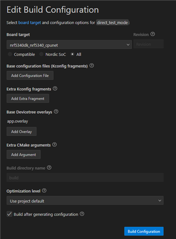
I can see that the correct prj.conf and overlay files are used according to the build output:
...
-- west build: generating a build system
Loading Zephyr default modules (Zephyr base).
-- Application: C:/ncs/v2.2.0/nrf/samples/bluetooth/direct_test_mode
-- Found Python3: C:/ncs/toolchains/v2.2.0/opt/bin/python.exe (found suitable exact version "3.8.2") found components: Interpreter
-- Cache files will be written to: C:/ncs/v2.2.0/zephyr/.cache
-- Zephyr version: 3.2.99 (C:/ncs/v2.2.0/zephyr)
-- Found west (found suitable version "0.14.0", minimum required is "0.7.1")
-- Board: nrf5340dk_nrf5340_cpunet
-- Found host-tools: zephyr 0.15.1 (C:/ncs/toolchains/v2.2.0/opt/zephyr-sdk)
-- Found toolchain: zephyr 0.15.1 (C:/ncs/toolchains/v2.2.0/opt/zephyr-sdk)
-- Found Dtc: C:/ncs/toolchains/v2.2.0/opt/bin/dtc.exe (found suitable version "1.4.7", minimum required is "1.4.6")
-- Found BOARD.dts: C:/ncs/v2.2.0/zephyr/boards/arm/nrf5340dk_nrf5340/nrf5340dk_nrf5340_cpunet.dts
-- Found devicetree overlay: app.overlay
-- Generated zephyr.dts: C:/ncs/v2.2.0/nrf/samples/bluetooth/direct_test_mode/build/zephyr/zephyr.dts
-- Generated devicetree_generated.h: C:/ncs/v2.2.0/nrf/samples/bluetooth/direct_test_mode/build/zephyr/include/generated/devicetree_generated.h
-- Including generated dts.cmake file: C:/ncs/v2.2.0/nrf/samples/bluetooth/direct_test_mode/build/zephyr/dts.cmake

Parsing C:/ncs/v2.2.0/nrf/samples/bluetooth/direct_test_mode/Kconfig
Loaded configuration 'C:/ncs/v2.2.0/zephyr/boards/arm/nrf5340dk_nrf5340/nrf5340dk_nrf5340_cpunet_defconfig'
Merged configuration 'C:/ncs/v2.2.0/nrf/samples/bluetooth/direct_test_mode/prj.conf'
Merged configuration 'C:/ncs/v2.2.0/nrf/samples/bluetooth/direct_test_mode/boards/nrf5340dk_nrf5340_cpunet.conf'
Configuration saved to 'C:/ncs/v2.2.0/nrf/samples/bluetooth/direct_test_mode/build/zephyr/.config'
Kconfig header saved to 'C:/ncs/v2.2.0/nrf/samples/bluetooth/direct_test_mode/build/zephyr/include/generated/autoconf.h'
-- The C compiler identification is GNU 12.1.0
-- The CXX compiler identification is GNU 12.1.0
-- The ASM compiler identification is GNU
-- Found assembler: C:/ncs/toolchains/v2.2.0/opt/zephyr-sdk/arm-zephyr-eabi/bin/arm-zephyr-eabi-gcc.exe

=== child image remote_shell - CPUAPP begin ===
loading initial cache file C:/ncs/v2.2.0/nrf/samples/bluetooth/direct_test_mode/build/remote_shell/child_image_preload.cmake
Loading Zephyr default modules (Zephyr base).
-- Application: C:/ncs/v2.2.0/nrf/samples/nrf5340/remote_shell
-- Found Python3: C:/ncs/toolchains/v2.2.0/opt/bin/python.exe (found suitable exact version "3.8.2") found components: Interpreter
-- Cache files will be written to: C:/ncs/v2.2.0/zephyr/.cache
-- Zephyr version: 3.2.99 (C:/ncs/v2.2.0/zephyr)
-- Found west (found suitable version "0.14.0", minimum required is "0.7.1")
-- Board: nrf5340dk_nrf5340_cpuapp
-- Found host-tools: zephyr 0.15.1 (C:/ncs/toolchains/v2.2.0/opt/zephyr-sdk)
-- Found toolchain: zephyr 0.15.1 (C:/ncs/toolchains/v2.2.0/opt/zephyr-sdk)
-- Found Dtc: C:/ncs/toolchains/v2.2.0/opt/bin/dtc.exe (found suitable version "1.4.7", minimum required is "1.4.6")
-- Found BOARD.dts: C:/ncs/v2.2.0/zephyr/boards/arm/nrf5340dk_nrf5340/nrf5340dk_nrf5340_cpuapp.dts
-- Found devicetree overlay: C:/ncs/v2.2.0/nrf/samples/bluetooth/direct_test_mode/child_image/remote_shell/boards/nrf5340dk_nrf5340_cpuapp.overlay
-- Generated zephyr.dts: C:/ncs/v2.2.0/nrf/samples/bluetooth/direct_test_mode/build/remote_shell/zephyr/zephyr.dts
-- Generated devicetree_generated.h: C:/ncs/v2.2.0/nrf/samples/bluetooth/direct_test_mode/build/remote_shell/zephyr/include/generated/devicetree_generated.h
-- Including generated dts.cmake file: C:/ncs/v2.2.0/nrf/samples/bluetooth/direct_test_mode/build/remote_shell/zephyr/dts.cmake
Parsing C:/ncs/v2.2.0/nrf/samples/nrf5340/remote_shell/Kconfig
Loaded configuration 'C:/ncs/v2.2.0/zephyr/boards/arm/nrf5340dk_nrf5340/nrf5340dk_nrf5340_cpuapp_defconfig'
Merged configuration 'C:/ncs/v2.2.0/nrf/samples/bluetooth/direct_test_mode/child_image/remote_shell/prj.conf'
Merged configuration 'C:/ncs/v2.2.0/nrf/subsys/partition_manager/partition_manager_enabled.conf'
Configuration saved to 'C:/ncs/v2.2.0/nrf/samples/bluetooth/direct_test_mode/build/remote_shell/zephyr/.config'
Kconfig header saved to 'C:/ncs/v2.2.0/nrf/samples/bluetooth/direct_test_mode/build/remote_shell/zephyr/include/generated/autoconf.h'
...
I let the firmware build and use the resulting merged_domains.hex to flash the nRF5340 via the Nordic Connect Programmer. Now I connect the UART of my custom board to a COM port on the PC and start the Direct Test Mode v3 tool. Using the same settings as pictured above, it works like a charm. I get the strong RSSI value on the chosen channel on my nRF52840 board using the RSSI viewer.
If I now make a power cycle of my custom board, the nRF does not respond the commands sent via the Direct Test Mode v3 tool.
What makes this even weirder is that if I now choose "Attach Debugger to Target" or "Debug without Flashing" in VSCode, it first shows that the nRF5340 has its readback protection enabled and asks me if I want to remove it and flash the device. I choose no. As expected the debugging or attaching process terminates. Now I do the exact same thing again, choosing either "Attach Debugger to Target" or "Debug without Flashing", depending on what I used before. It starts the debugging session without telling me that the nRF5340 is readback protected. If I now try the Direct Test Mode v3 tool again, it works...
I cannot explain what is happening here. Any help is deeply appreciated.
Best regards,
Alex

