
Hi,
I have a custom board similar to the thingy91.
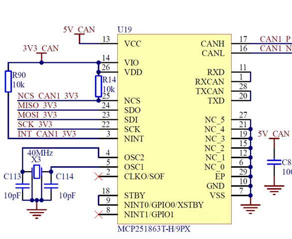
I use two MCP251863 (same as MCP2518FD with an integrated tranceiver) on the spi3.
schematic
device tree
/ {
	model = "custom thingy nRF9160";
	compatible = "nordic,asl01-nrf9160";

	chosen {
		zephyr,console = &uart0;
		zephyr,shell-uart = &uart0;
		zephyr,uart-mcumgr = &uart0;
		zephyr,canbus = &can1;
	};

	buttons {
		compatible = "gpio-keys";

		button0: button_0 {
			gpios = <&gpio0 26 (GPIO_PULL_UP | GPIO_ACTIVE_LOW)>;
			label = "Button 1";
		};
	};

	leds {
		compatible = "gpio-leds";
		red_led: led_1 {
			gpios = <&gpio0 13 0>;
			label = "RGB red channel";
		};
		green_led: led_2 {
			gpios = <&gpio0 9 0>;
			label = "RGB green channel";
		};
		blue_led: led_3 {
			gpios = <&gpio0 14 0>;
			label = "RGB blue channel";
		};
	};

	pwmleds {
		compatible = "pwm-leds";
		pwm_led0: pwm_led_0 {
			pwms = <&pwm0 0 PWM_MSEC(8) PWM_POLARITY_NORMAL>;
		};
		pwm_led1: pwm_led_1 {
			pwms = <&pwm0 1 PWM_MSEC(8) PWM_POLARITY_NORMAL>;
		};
		pwm_led2: pwm_led_2 {
			pwms = <&pwm0 2 PWM_MSEC(8) PWM_POLARITY_NORMAL>;
		};
	};

	nrf52840_reset: gpio-reset {
		compatible = "nordic,asl01-nrf52840-reset";
		status = "okay";
		gpios = <&gpio0 10 GPIO_ACTIVE_LOW>;
	};

	aliases {
		sw0 = &button0;
		led0 = &red_led;
		led1 = &green_led;
		led2 = &blue_led;
		pwm-led0 = &pwm_led0;
		pwm-led1 = &pwm_led1;
		pwm-led2 = &pwm_led2;
		rgb-pwm = &pwm0;
		mcuboot-button0 = &button0;
		mcuboot-led0 = &blue_led;
	};
};

&adc {
	status = "okay";
};

&gpiote {
	status = "okay";
};

&gpio0 {
	status = "okay";
};

/* PWM0 is intended for RGB LED control */
&pwm0 {
	status = "okay";
	pinctrl-0 = <&pwm0_default>;
	pinctrl-1 = <&pwm0_sleep>;
	pinctrl-names = "default", "sleep";
};

&spi3 {
	compatible = "nordic,nrf-spim";
	status = "okay";
	cs-gpios = <&gpio0 0 GPIO_ACTIVE_LOW>;

	pinctrl-0 = <&spi3_default>;
	pinctrl-1 = <&spi3_sleep>;
	pinctrl-names = "default", "sleep";

	can1: mcp251xfd@0 {
		compatible = "microchip,mcp251xfd";
		status = "okay";

		spi-max-frequency = <18000000>;
		int-gpios = <&gpio0 31 GPIO_ACTIVE_LOW>;
		reg = <0x0>;
		osc-freq = <40000000>;

		bus-speed-data = <1000000>;
		bus-speed = <500000>; // 500Kbits/s
		sample-point = <875>;
		sample-point-data = <875>;
	};
};
prj.conf
CONFIG_SPI=y
CONFIG_CAN=y
CONFIG_CAN_FD_MODE=y
CONFIG_CAN_MCP251XFD=y
Q1: how to add both MCP to my device tree ?
Q2: do I add the tranceiver to the device tree, if yes, how to do so ?
Q3: how to enable disble the tranceiver ?
thanks for your time,
