DevAcademy intermediate Lesson 5 Exercise 2 alternative RPi Display with nrf9161DK

I have been sitting with this problem for almost 2 weeks and have tried alot of different thing but without anything working,

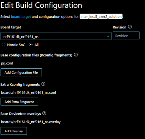
Im using VS code with the nrf9161 and it has the version: "Manage toolchains v2.7.0 and "Manage west workspace v2.6.1"

Just compiling the code i get these warnings:

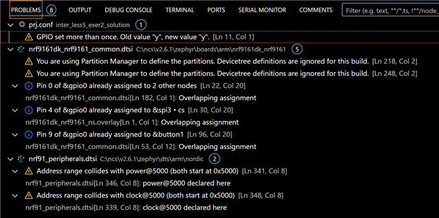
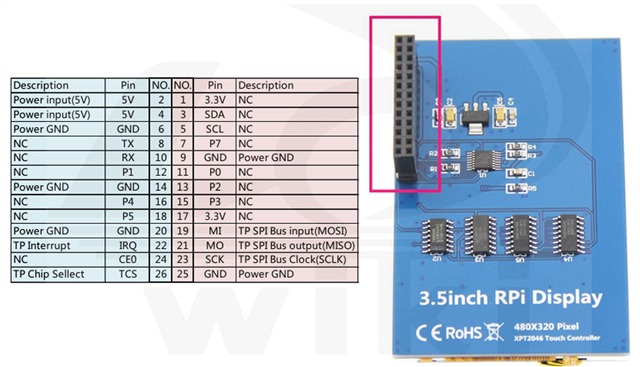
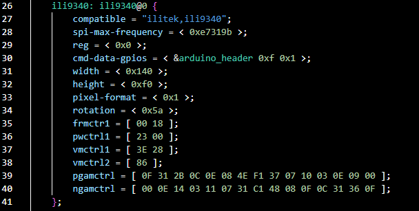
I want to implement the code with the 3.5Inch RPi Display, it uses different driver "ILI9486" which is not in zephyrs basic lib. 

What would i have to change in the current example to make it work or what part would i look into, to make it work?

Where im stuck:

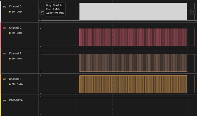
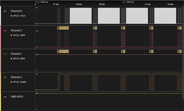
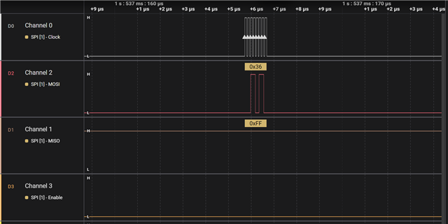
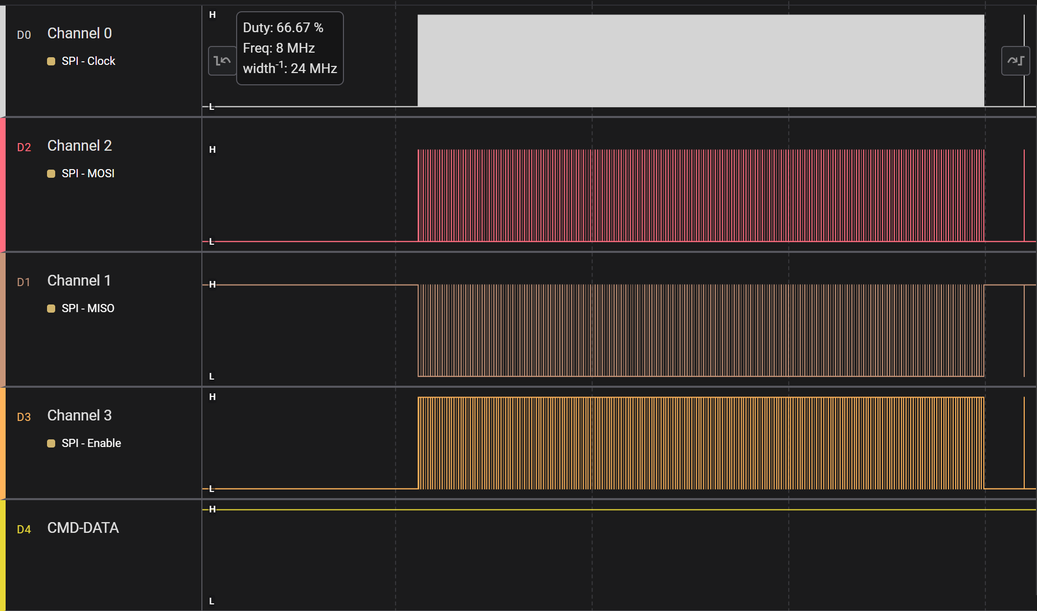
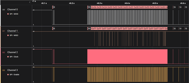
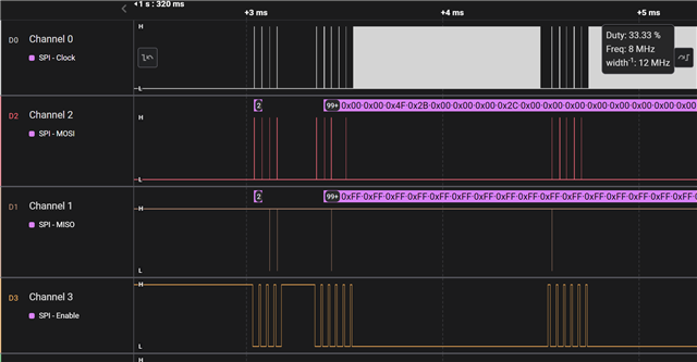
Im not sure if im getting the the right output from pin 11, 12 and 13 (clk, mosi, miso) when using a logic analyzer:

Also the D/CX and CS should be on pin 10 and 15, but not getting any change of state when putting them into the logic analyzer

cs-gpios = < &arduino_header 0x10 0x1 >, < &arduino_header 0xa 0x1 >;
cmd-data-gpios = < &arduino_header 0xf 0x1 >;

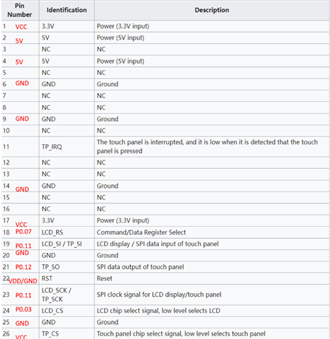
The spec of the display:

Display 3.5 inch TFT LCD Touch Screen Monitor 480 x 320 for RPi with Touch PenFeatures:● The display has a resolution of 480 x 320, which is perfectly sufficient for small projects.

Resistive touch control.

● The display is compatible with RPi A, B, A+, B+, 2B, 3B, 3B+, 4B.

● GPIO pins remain free to address other devices.

Driver provided (works directly with your own Raspbian/Ubuntu).

Supports RP-bian system, Ubuntu system, Kali Linux system.LCD type: TFT.

LCD interface: SPI (Fmax: 32 MHz)

Touch screen type: resistor.

Touchscreen controller: xpt2046.

Colours: 65536.

Driver IC: ILI9486.

Backlight: LED.

Resolution: 320 x 480 (pixels).

Backlight current: 120mA

Power dissipation: 0.13 A x 5 V.

Active area: 48.96x73.44 (mm)

Product size: 85.42 x 55.60 mm.

Package size: 118 x 72 x 34 mm.

Coarse weight (package includes): 75 (g)Box contents:

1 x 3.5 inch touch screen for RPi.

1 x touch pen.


Parents
  • Hi,


    By default, the nRF9161-DK is using 1.8V VDD GPIO voltage. This can be changed in the board configurator in nRF connect for desktop:

    https://docs.nordicsemi.com/bundle/nrf-connect-board-configurator/page/updating.html

    Could you try setting "VDD for GNSS and LEDs" to match the required voltage of your display (ie. 3.3V) and see if the display starts responding over SPI then?


    Kind regards,

    Håkon

  • Hi Håkon

    Thx for the quick reply. I tried changing the setting "VDD for GNSS and LEDs" to 3.3V, it was on 3.0V before changing it.

    But it is still not showing anything. I also tried to change the cmd-data to pin P0.03 and CS to pin P0.07 so there was no conflict with those pins, but still without any result.

    When measuring the voltage on the pins: CS is 3.3V but cmd-data are only 0V no matter if i try the default pins or not.

    The display only works with 5V, then trying 3.3V the display does not light up.

    This is the output im getting when the display is connected, still only lights up white.

    /Egil                                                                                                                                                                                                                                                 

  • Hi Egil,


    Can you share the zoomed in data and response from the board?

    EgilCL said:
    cmd-data to pin

    Which pin is this? Is this what is mapped to the "IRQ" pin on the 20-pin header?

    Note that this is not a display that I have tried before, so I am quite blank in terms of how this maps to the header that you posted.


    Is there any log output from the firmware that can help here?


    Kind regards,

    Håkon

Reply
  • Hi Egil,


    Can you share the zoomed in data and response from the board?

    EgilCL said:
    cmd-data to pin

    Which pin is this? Is this what is mapped to the "IRQ" pin on the 20-pin header?

    Note that this is not a display that I have tried before, so I am quite blank in terms of how this maps to the header that you posted.


    Is there any log output from the firmware that can help here?


    Kind regards,

    Håkon

Children
  • Thx for taking your time to help me.

    So i guess the first thing is to make sure the SPI works right?

    So just to be sure, the example has the piunouts

    SCK - P0.13

    MISO - P0.12

    MOSI - P0.11

    cmd-data - P0.09

    CS- P0.04

    is this correct?

    The base exercise should work out of the box sins it also has an overlay file dedicated to nrf9161?

    Should there be conflicting pin from this exercise?

    My board configuration is this:

    The cmd-data pin is this one in the overlay file:

    My pinout (i tried with both default pins and custom ones (CS and cmd)):

    To answer your question: IRQ is connecting to VDD or GND, didnt know which would work, but with no luck for now.

  • some screenshots of the output:

    The  first 4 hex from mosi is: 0x36, 0x28, 0x3A, 0x66

  • Hi,


    Could you .zip the saleae logic file and share it here?

    In the picture that you attached yesterday:


    There are toggling on the MISO line, but with the resolution of the image, it is hard to say what is happening.

    EgilCL said:
    Should there be conflicting pin from this exercise?

    There can be an issue if you use the button. Ensure that CONFIG_DK_LIBRARY=n.


    Is there any runtime logging that is printed when you run the firmware?


    Are you using ncs v2.7.0 or v2.6.2? In v2.7.0, which is based on zephyr 3.6, the way to populate a display has changed:

    https://github.com/nrfconnect/sdk-zephyr/blob/v3.6.99-ncs2/doc/releases/migration-guide-3.6.rst#display


    Kind regards,

    Håkon

  • nrf9161DK_SPI_Display.zip

    * The saleae logic file output is with custom gpios for CS and CMD.

    *I put "CONFIG_DK_LIBRARY=n" into the prj.conf but it still shows the conflict between pins.

    *I changed to v2.61, but with no difference for now.

    *Im still fairly new to the nrf and vscode, so im unsure how to get the logs? here are the output from the terminal:

  • Hi,


    The trace does not show any activity on the MISO (master in - slave out) line, which the display should use to respond to the nRF host. 

    EgilCL said:
    Im still fairly new to the nrf and vscode, so im unsure how to get the logs? here are the output from the terminal:

    Logs are by default outputted on the UART. You can open up your favorite terminal (putty, teraterm, nrf serial etc) and connect to the COM-port with 115200 baud rate, and you should get a log output.


    EgilCL said:
    *I put "CONFIG_DK_LIBRARY=n" into the prj.conf but it still shows the conflict between pins.

    vscode will warn you about the conflict, as the devicetree entires do indeed conflict, but if you do not use the LEDs/Buttons, the GPIOs will be unused.


    Have you checked the datasheet of your display driver to see if this is compatible with the ilitek9340?


    Kind regards,

    Håkon

Related