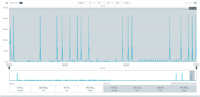
IOVDD is constantly high

Hello,

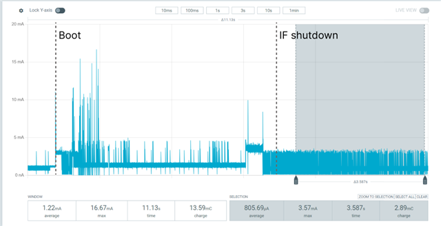
I am using the nRF5340-DK board along with the nRF7002-EK companion. I noticed that current consumption was high while running my MQTT application on this setup, particularly at IOVDD. Current is averaging 700-800 uA at IOVDD while powered through the USB and it seems pretty constant, measured from both a PPKII and an ammeter. From reading the docs, it seems like the switch on the nRF7002-DK which is tied to GPIO P1.00 on the nRF5340 should activate/deactivate that switch in order to disconnect IOVDD when not necessary. However, it seems like this GPIO is maintained high all the time.
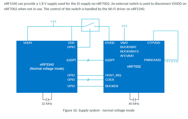
Do I need to configure the application in any particular way to enable switching? I have tried those configs with no success

CONFIG_PM_DEVICE=y
CONFIG_NRF_WIFI_LOW_POWER=y
CONFIG_NRF700X_QSPI_LOW_POWER=y
I have also tried running sample WiFi Shell and IOVDD is also maintained high all the time.
Thanks in advance
Parents
  • Hi,


    Are you running the PM_DEVICE API to place the bus interface in suspend mode?

    int ret = pm_device_action_run(flash_dev, PM_DEVICE_ACTION_SUSPEND);
    if (ret) {
        /* Handle error */
    }
    ...
    ret = pm_device_action_run(flash_dev, PM_DEVICE_ACTION_RESUME);
    if (ret) {
        /* Handle error */
    }


    Or do you want to completely shut down the nRF7002? If yes, then there's a sample here that shows this use-case:

    https://github.com/nrfconnect/sdk-nrf/blob/v2.7.0/samples/wifi/shutdown/src/main.c


    Kind regards,

    Håkon

  • Hi,

    to answer yout question, I would like the Wi-Fi chip to consume as little power as possible whenever it goes into extended power saving mode, after connecting to the AP. Ideally, I would remain connected to the AP.


    I have tried the Wi-Fi shutdown sample as you suggested, I built it "as is" on my target using the following build command and i flashed it.

    west build -d build_default -b nrf5340dk_nrf5340_cpuapp -p -- -DSHIELD=nrf7002ek

    As for the nRF5340 SoC, when measuring current at VDD_nRF using the PPK2, the average value is 805 uA

    however, this value goes down to 2 uA when we disable serial communication and logging by setting those config values:


    CONFIG_SERIAL=n 
    CONFIG_LOG=n

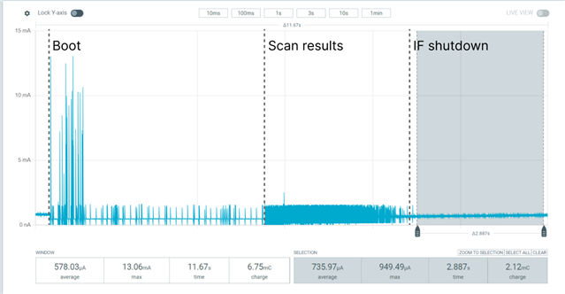
    However when measuring current on the IOVDD pin of the nRF7002-DK using the PPK2, I do not observe any form of shutdown. Current at this pin is still 735 uA. 


     Is this normal behavior, for that particular example? It seems like the Wifi chip has a pretty high power consumption for a device that should be in shutdown state.

    And also, I would like to know, because it does not seem clear to me

    - Is the IOVDD switch on nRF7002-EK and tied to GPIO P1.00 (IOVDD_EN) meant to be operated manually by the application code or is it handled by the driver? I thought that this sentence (found in Hardware and layout )

    "The control of the switch is handled by the Wi-Fi driver on nRF5340."

    Meant that I did not have to manually control the power mode of the nRF7002. In response to your comment about the PM API.

    Thanks in advance

  • Hi,

    simon belanger said:
    However when measuring current on the IOVDD pin of the nRF7002-DK using the PPK2, I do not observe any form of shutdown. Current at this pin is still 735 uA. 

    Did you try the shutdown sample to completely shut down the nRF7002 when testing?


    It should show this in the terminal:

    *** Booting nRF Connect SDK v2.7.0-5cb85570ca43 ***
    *** Using Zephyr OS v3.6.99-100befc70c74 ***
    [00:00:00.560,211] <inf> shutdown: Starting nrf7002dk with CPU frequency: 64 MHz
    
    [00:00:00.563,690] <inf> shutdown: Scan requested
    
    Num  | SSID                             (len) | Chan | RSSI | Security | BSSID
    long list of APs in my area
    
    
    [00:00:05.339,019] <inf> shutdown: Scan request done
    
    [00:00:05.352,600] <inf> shutdown: Interface down


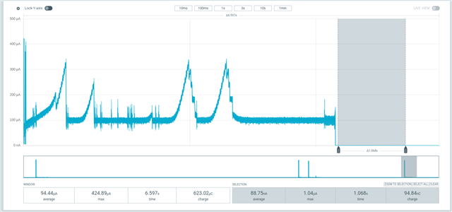
    And will have a current profile similar to this on IOVDD:


    simon belanger said:

    - Is the IOVDD switch on nRF7002-EK and tied to GPIO P1.00 (IOVDD_EN) meant to be operated manually by the application code or is it handled by the driver? I thought that this sentence (found in Hardware and layout )

    "The control of the switch is handled by the Wi-Fi driver on nRF5340."

    Meant that I did not have to manually control the power mode of the nRF7002. In response to your comment about the PM API.

    It will be handled if you take down the net interface, which again calls the deinit functions in the driver itself:

    https://github.com/nrfconnect/sdk-nrf/blob/v2.7.0/drivers/wifi/nrf700x/src/qspi/src/rpu_hw_if.c#L204


    Since the driver disconnects the GPIO, it is important that you have defined the device in devicetree with a pull-down:

    https://github.com/nrfconnect/sdk-nrf/blob/v2.7-branch/boards/shields/nrf7002ek/nrf7002ek.overlay#L41


    Kind regards,

    Håkon

  • Hi,

    Did you try the shutdown sample to completely shut down the nRF7002 when testing?

    Sorry if I was not clear. The current plots I reported in my last message were all taken while running the Wi-Fi shutdown sample. In the terminal, I had this 

    *** Booting nRF Connect SDK v2.7.0-5cb85570ca43 ***
    *** Using Zephyr OS v3.6.99-100befc70c74 ***
    [00:00:00.283,508] <inf> wifi_nrf_bus: SPIM spi@a000: freq = 8 MHz
    [00:00:00.283,538] <inf> wifi_nrf_bus: SPIM spi@a000: latency = 0
    [00:00:00.482,269] <inf> shutdown: Starting nrf5340dk with CPU frequency: 64 MHz
    
    [00:00:00.486,083] <inf> shutdown: Scan requested
    
    Num  | SSID                             (len) | Chan | RSSI | Security | BSSID
    ...
    
    [00:00:05.580,078] <inf> shutdown: Scan request done
    
    [00:00:05.593,627] <inf> shutdown: Interface down

    but as I showed, you, IOVDD never goes down to the sub uA range while running this sample. Even when the interface shuts down, it remains in the 700 uA range. So that means I do not get the same current profile you get. 

    I thinks there is something not behaving correctly on my setup and I do not know what, since we test the same thing and do not get the same outcome.

    Since the driver disconnects the GPIO, it is important that you have defined the device in devicetree with a pull-down:

    I am using the Cmake argument `-DSHIELD=nrf7002ek` when building the code, which adds the following to my devicetree file (zephyr.dts)

    				nrf700x: nrf7002@0 {
    					compatible = "nordic,nrf700x-spi";
    					status = "okay";
    					reg = < 0x0 >;
    					spi-max-frequency = < 0x7a1200 >;
    					iovdd-ctrl-gpios = < &arduino_header 0x6 0x20 >;
    					bucken-gpios = < &arduino_header 0x7 0x20 >;
    					host-irq-gpios = < &arduino_header 0xd 0x0 >;
    				};
    			};

    I believe that my devicetree configuration is correct.

    Am I missing something?

    Best regards,

    Simon

  • Hi,

    You mention that you measure 2 uA with the nRF5340-DK + nRF7002-EK:

    simon belanger said:
    however, this value goes down to 2 uA when we disable serial communication and logging by setting those config values:

    And the problem arises when you use the nRF7002-DK:

    simon belanger said:
    However when measuring current on the IOVDD pin of the nRF7002-DK using the PPK2, I do not observe any form of shutdown. Current at this pin is still 735 uA. 

    But, based on your newest logs, it seems that you are using nRF5340-DK + nRF7002-EK?

    Can you please share a picture of how you setup your test?


    If you are measuring the board as a whole, the current consumption of the nRF5340 will be added, and based on your prints; I assume that UART / Logging is still running? You will have to disable/turn off that to enter low power mode (ie. sub 10 uA) sleep.


    Kind regards,

    Håkon

  • Hi,

    However when measuring current on the IOVDD pin of the nRF7002-DK using the PPK2, I do not observe any form of shutdown. Current at this pin is still 735 uA. 

    Sorry I made a mistake, I meant the nRF7002-EK! The whole time my setup has been nRF5340-DK + nRF7002-EK.

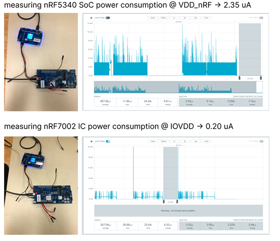
    I just tried performing the current measurements again for the Wi-Fi shutdown sample (with serial comm disabled). I measured VDD_nRF on the nRF5340-Dk board and IOVDD on the nRF7002-EK board. Here is what I got

    which is what's expected. I probably did something wrong in my first measurement. RIght now, this confirms that the sample can shutdown the Wi-Fi chip in order to bring down power consumption.

    Now, I am wondering how I can implement this behavior on my application. Will I have to reconnect to the AP if I bring up the interface after I put it into shutdown? For example, If my device is connected to an AP with a listen interval that makes it exchange data only once in an hour, could I bring the interface down in the meantime?

    thanks in advance,

    Simon


Reply
  • Hi,

    However when measuring current on the IOVDD pin of the nRF7002-DK using the PPK2, I do not observe any form of shutdown. Current at this pin is still 735 uA. 

    Sorry I made a mistake, I meant the nRF7002-EK! The whole time my setup has been nRF5340-DK + nRF7002-EK.

    I just tried performing the current measurements again for the Wi-Fi shutdown sample (with serial comm disabled). I measured VDD_nRF on the nRF5340-Dk board and IOVDD on the nRF7002-EK board. Here is what I got

    which is what's expected. I probably did something wrong in my first measurement. RIght now, this confirms that the sample can shutdown the Wi-Fi chip in order to bring down power consumption.

    Now, I am wondering how I can implement this behavior on my application. Will I have to reconnect to the AP if I bring up the interface after I put it into shutdown? For example, If my device is connected to an AP with a listen interval that makes it exchange data only once in an hour, could I bring the interface down in the meantime?

    thanks in advance,

    Simon


Children
  • Hi,

    simon belanger said:
    which is what's expected. I probably did something wrong in my first measurement. RIght now, this confirms that the sample can shutdown the Wi-Fi chip in order to bring down power consumption.

    I am glad to hear that the measurements work as expected now!


    simon belanger said:
    Now, I am wondering how I can implement this behavior on my application. Will I have to reconnect to the AP if I bring up the interface after I put it into shutdown? For example, If my device is connected to an AP with a listen interval that makes it exchange data only once in an hour, could I bring the interface down in the meantime?

    The shutdown sample will effectively be a full power-off of the nRF7002, ie. by turning off the voltage to it.

    If you then wake it up again, it means a full re-connect and re-initialization of the net interface.

    If you take the STA sample, which enables DTIM power saving by default, you should see a similar VDDIO current draw like this:

    This is the wifi/sta sample, where I connect to a network. The driver will dynamically draw current based on communication.

    Each peak is reflected for each transmission over the SPI interface.


    Now, if you include the host controller into the current measurement, you will have to ensure that interfaces such as the logger (serial) is disabled.


    Kind regards,

    Håkon

  • Hi,

    If you take the STA sample, which enables DTIM power saving by default

    Ok thats looks more like what I am trying to do with my application, where my device (STA) stays connected to the AP but consumes less because it is in power saving mode. 

    I tried the Wi-Fi Station sample to make sure I could get the power consumption you measured. I built the sample for my target using the following command and then flashed it. The Wi-Fi credentials were configured as described in docs.nordicsemi.com/.../README.html

    west build -b nrf5340dk_nrf5340_cpuapp -p -- -DSHIELD=nrf7002ek

    The serial monitor indicates that the sample is working as expected. I also see LED 1 blinking when the device connects to the AP.

    *** Booting nRF Connect SDK v2.7.0-5cb85570ca43 ***
    *** Using Zephyr OS v3.6.99-100befc70c74 ***
    [00:00:00.697,753] <inf> net_config: Initializing network
    [00:00:00.697,784] <inf> net_config: Waiting interface 1 (0x20000ee0) to be up...
    [00:00:00.697,937] <inf> net_config: IPv4 address: 192.168.1.99
    [00:00:00.697,998] <inf> net_config: Running dhcpv4 client...
    [00:00:00.698,852] <inf> sta: Starting nrf5340dk with CPU frequency: 64 MHz
    [00:00:01.699,035] <inf> sta: Static IP address (overridable): 192.168.1.99/255.255.255.0 -> 192.168.1.1
    [00:00:01.699,066] <inf> sta: Waiting for Wi-Fi to be ready
    [00:00:03.250,915] <inf> wifi_mgmt_ext: Connection requested
    [00:00:03.250,946] <inf> sta: Connection requested
    [00:00:03.250,976] <inf> sta: ==================
    [00:00:03.251,007] <inf> sta: State: SCANNING
    [00:00:03.551,177] <inf> sta: ==================
    [00:00:03.551,208] <inf> sta: State: SCANNING
    [00:00:03.851,348] <inf> sta: ==================
    [00:00:03.851,379] <inf> sta: State: SCANNING
    [00:00:04.151,519] <inf> sta: ==================
    [00:00:04.151,550] <inf> sta: State: SCANNING
    [00:00:04.451,690] <inf> sta: ==================
    [00:00:04.451,721] <inf> sta: State: SCANNING
    [00:00:04.751,861] <inf> sta: ==================
    [00:00:04.751,892] <inf> sta: State: SCANNING
    [00:00:05.052,032] <inf> sta: ==================
    [00:00:05.052,062] <inf> sta: State: SCANNING
    [00:00:05.352,203] <inf> sta: ==================
    [00:00:05.352,233] <inf> sta: State: SCANNING
    [00:00:05.652,374] <inf> sta: ==================
    [00:00:05.652,404] <inf> sta: State: SCANNING
    [00:00:05.952,545] <inf> sta: ==================
    [00:00:05.952,575] <inf> sta: State: SCANNING
    [00:00:06.252,716] <inf> sta: ==================
    [00:00:06.252,746] <inf> sta: State: SCANNING
    [00:00:06.552,886] <inf> sta: ==================
    [00:00:06.552,917] <inf> sta: State: SCANNING
    [00:00:06.853,057] <inf> sta: ==================
    [00:00:06.853,088] <inf> sta: State: SCANNING
    [00:00:07.153,228] <inf> sta: ==================
    [00:00:07.153,259] <inf> sta: State: SCANNING
    [00:00:07.453,399] <inf> sta: ==================
    [00:00:07.453,430] <inf> sta: State: AUTHENTICATING
    [00:00:07.652,282] <inf> sta: Connected
    [00:00:07.759,185] <inf> sta: ==================
    [00:00:07.759,185] <inf> sta: State: COMPLETED
    [00:00:07.759,216] <inf> sta: Interface Mode: STATION
    [00:00:07.759,246] <inf> sta: Link Mode: WIFI 5 (802.11ac/VHT)
    [00:00:07.759,277] <inf> sta: SSID: GPHY
    [00:00:07.759,338] <inf> sta: BSSID: 9C:53:22:46:AE:2B
    [00:00:07.759,368] <inf> sta: Band: 5GHz
    [00:00:07.759,368] <inf> sta: Channel: 153
    [00:00:07.759,399] <inf> sta: Security: WPA2-PSK
    [00:00:07.759,429] <inf> sta: MFP: Optional
    [00:00:07.759,429] <inf> sta: RSSI: -32
    [00:00:10.679,595] <inf> net_dhcpv4: Received: 192.168.68.110
    [00:00:10.679,779] <inf> net_config: IPv4 address: 192.168.68.110
    [00:00:10.679,779] <inf> net_config: Lease time: 7200 seconds
    [00:00:10.679,809] <inf> net_config: Subnet: 255.255.255.0
    [00:00:10.679,870] <inf> net_config: Router: 192.168.68.1
    [00:00:10.679,992] <inf> sta: DHCP IP address: 192.168.68.110

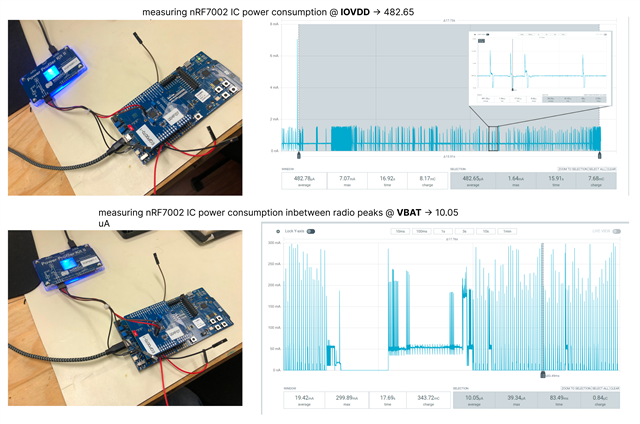
    However, there is something wrong with my current consumption. Net VBAT seems right, I can observe the Wi-Fi beacons and 10 uA in between them. But net IOVDD shows a mean current of around 500 uA. There seems to be a DC current draw of 500 uA on IOVDD and I do not know why. I do not think IOVDD is behaving the way it should.


    Also, I am using SDK version 2.7.0, and I took the sample from that version of the SDK.

    Simon

  • Hi Simon,


    Thank you for the detailed description and your patience in this matter.

    I can confirm that there is a pin conflict on the nRF5340-DK, where the pins P1.01/P1.00 is connected to the SEGGER IC, specifically for the RXD/TXD handling for the uart bridge, which is causing an incorrect power up sequence on "BUCK_EN" and "IOVDD_EN"

    The fix for this is unfortunately not straight forward, which is to break the SB29 and SB30:

    https://docs.nordicsemi.com/bundle/ug_nrf5340_dk/page/UG/dk/solder_bridge.html


    This will then render that specific UART port enumerated in the OS, unavailable.


    Kind regards,

    Håkon

  • Hi,

    so by breaking solderbridges SB29 and SB30, UART1 of the nRF5340 SoC is disconnected from the Interface MCU (which is another nRF5340 chip and not a SEGGER IC on nRF534-DK by the way). Also, I thought that having the DK in mode nRF_ONLY meant that these connections were broken anyway?

    Anyway, I broke the solderbridges and I still measure a 500 uA power consumption for the nRF7002 IOVDD. So this advice did not solve the issue. 

    Will that consumption issue happen with nRF7002-DK? If this board does not have that issue, I might use it instead if that can be simpler.

    Simon

  • Hi Simon,


    My apologies for the inconvenience.

    simon belanger said:
     Also, I thought that having the DK in mode nRF_ONLY meant that these connections were broken anyway?

    I agree, there is something else in addition that is drawing current here. I'll report this internally, so that we can update our docs in this matter.

    simon belanger said:
    Will that consumption issue happen with nRF7002-DK? If this board does not have that issue, I might use it instead if that can be simpler.

    I can confirm that the nRF7002-DK does not have this current consumption issue.


    Kind regards,

    Håkon

Related