Flash Partition Management with Trusted Firmware-M

Backround: We are planning to use TF-M with a two-stage bootloader (NSIB & MCUBoot) using dual-slots for secure and non-secure images. We need to support configurable fixed flash partitions (i.e. for event or configuration storage) and would like to retain the option to use an external flash in the future.

I have read through the nRF Connect SDK documentation, however it is not clear to me how the Partition Managed is used to configure fixed flash partitions for targets using TF-M. Could you please provide an example partition configuration on the nRF9160 (using internal flash) with: dual-slots for secure / non-secure images, secure storage (i.e. certificates), event storage (for telemetry) and configuration?

Parents
  • I would like to re-open this ticket as I have a few follow-up questions.

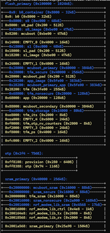
    When I run the partition_manager_report, I receive the following output:

    I understand the following about the partition layout:

    • B0 (0x0): This is the Nordic Secure Immutable Bootloader (NSIB).
    • S0 (0x8000) and S1 (0x18000): These are MCUBoot partitions.

    However, the following partitions are not entirely clear to me:

    • mcuboot_primary (0x28000)
    • tfm_secure (0x28000)
    • app_image (0x28200)
    • mcuboot_primary_app (0x28200)
    • tfm (0x28200)
    • tfm_nonsecure (0x68000)
    • app (0x68000)
    • mcuboot_secondary (0x88000)

    My observation is that some of these partitions seem to overlap, which leads me to believe they might be overlaid for ease of use in code. For example, referring to app_image instead of calculating mcuboot_primary + 0x200.

    Could you clarify the exact purpose of these partitions?

    Additionally, I would like to understand where the code I compile will eventually reside. For example, where are pending updates stored (assume we're using swap w/ scratch)?

    Finally, my assumption is that the boot sequence is as follows: NSIB loads MCUBoot, which then loads TFM, and finally, the user application is loaded. Is this assumption correct?

Reply
  • I would like to re-open this ticket as I have a few follow-up questions.

    When I run the partition_manager_report, I receive the following output:

    I understand the following about the partition layout:

    • B0 (0x0): This is the Nordic Secure Immutable Bootloader (NSIB).
    • S0 (0x8000) and S1 (0x18000): These are MCUBoot partitions.

    However, the following partitions are not entirely clear to me:

    • mcuboot_primary (0x28000)
    • tfm_secure (0x28000)
    • app_image (0x28200)
    • mcuboot_primary_app (0x28200)
    • tfm (0x28200)
    • tfm_nonsecure (0x68000)
    • app (0x68000)
    • mcuboot_secondary (0x88000)

    My observation is that some of these partitions seem to overlap, which leads me to believe they might be overlaid for ease of use in code. For example, referring to app_image instead of calculating mcuboot_primary + 0x200.

    Could you clarify the exact purpose of these partitions?

    Additionally, I would like to understand where the code I compile will eventually reside. For example, where are pending updates stored (assume we're using swap w/ scratch)?

    Finally, my assumption is that the boot sequence is as follows: NSIB loads MCUBoot, which then loads TFM, and finally, the user application is loaded. Is this assumption correct?

Children
No Data
Related